


4. CONTROLS
4.1 INTEGRATED CONTROL
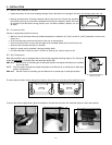
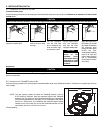
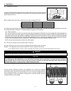
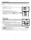
All units are equipped with an integrated control, located under the unit, in front of the electrical
compartment. Use the push button (1) to control the unit. The LED (2) will then shows on
which mode the unit is in.
WARNING
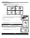
Risk of electric shock. Before performing
any maintenance or servicing, always
disconnect the unit from its power source.
AVERTISSEMENT
Danger d’électrocution. Débranchez
toujours l’appareil avant d’entreprendre
des travaux d’entretien ou de réparation.
CAUTION
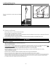
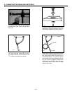
Unscrew both screws to open the electrical
compartment. To completely remove, detach
from its retention wire inside.
ATTENTION
Dévisser les deux vis pour ouvrir le compartiment
électrique. Pour retirer complètement, le
détacher de son fil de rétention intérieur.
No light OFF or remote controled
Amber light LOW speed
Green ligh HIGH speed
Blinking light See User Manual
Sans lumière Arrêté ou contrôlé
par contrôle mural
Lumière ambre Basse vitesse
Lumière verte Haute vitesse
Clignotant Voir guide d’utilisation
VD0182
1
2
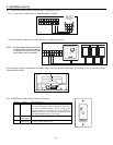
Refer to table below to see how to operate the unit using its integrated control.
PRESS ON PUSH BUTTON
LED COLOR RESULTS
ONCE
AMBER UNIT IS ON LOW
SPEED
TWICE
GREEN UNIT IS ON HIGH
SPEED
THREE TIMES NO LIGHT
UNIT IS OFF
If a problem occurs during the unit operation, its integrated control LED (2) will blink.The color of the blinking light depends on the type
of error detected. Refer to
Section 11 Troubleshooting
on last page for further details.
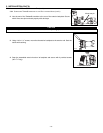
4.1.1 BOOT SEQUENCE
The unit boot sequence is similar to a personnal computer boot sequence. Each times the unit is plugged after being unplugged, or
after a power failure, the unit will perform a 30-second booting sequence before starting to operate. During the booting sequence, the
integrated control LED will light GREEN or AMBER for 5 seconds, and then will shut off for 2 seconds.After that, the LED will light RED
for the rest of the booting sequence. During this RED light phase, the unit is checking and resetting the motorized damper position.
Once the motorized damper position completely set, the RED light turns off and the booting sequence is done.
NOTE: No command will be taken until the unit is fully booted.
For more convenience, this unit can also be controlled using an optional main wall control.
NOTES: 1.The integrated control must be turned OFF to use an optional main control.
2.If an optional auxiliary control is used, if activated, this auxiliary control will override the optional main control.
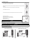
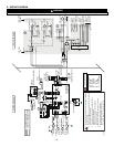
4.2 ELECTRICAL CONNECTION TO OPTIONAL WALL CONTROLS
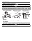
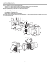
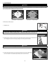
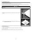
Use the terminal connector included in the installation kit to perform the electrical
connection for main and optional wall controls. Check if all wires are correctly inserted in
their corresponding holes in the terminal block. (A wire is correctly inserted when its
orange receptacle is lower than another one without wire. On picture beside, wire A is
correctly inserted, but not wire B.)
CAUTION
Never install more than one optional main wall control per unit. Make sure that the wires do not short-circuit between themselves
or by touching any other components on the wall control. Avoid poor wiring connections. To reduce electrical interference
(noise) potential, do not run wall control wiring next to control contactors or near light dimming circuits, electrical motors,
dwelling/building power or lighting wiring, or power distribution panel.
WARNING
Always disconnect the unit before making any connections. Failure in disconnecting power could result in electrical shock or
damage of the wall control or electronic module inside the unit.
0
!
A
B
VE0106
- 17 -