


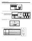
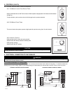
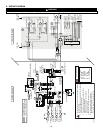
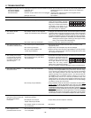

6. WIRING DIAGRAM
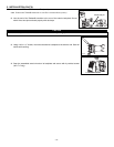
WARNING
Risk of electrical shocks. Before performing any maintenance or servicing, always disconnect the unit from its power source.
!
Field wiring
remote control
(see notes 3 & 4)
120 V, 60 Hz
W1
J5
J7
J6
J4
ELECTRONIC
ASSEMBLY
1
2
3
1
2
1
2
1
2
3
1 2 3 4
1 2
1 2 3 4 5
1 2 3 4 5
J8
J9
J11
J10
1 2
J12
J13
J14
10
9
8
7
6
5
4
3
2
1
B
24 V
class 2
9.5 V
class 2
120V, 60Hz
Neutral
120 V, 60Hz
Line
CPU
K2
K4
K5
J5-2
J10-1 J10-2
Line voltage factory wiring
Class 2 low voltage factory wiring
Class 2 low voltage field wiring
See note 1
120 V
90 V
68 V
neutral
Door interlock switch
(magnetically actuated
Exhaust fan
motor
1 2 3 4 5 1 2
1 2
J3
J2
J1
t˚
Damper motor
BK
Override
switch
Furnace blower interlock
J14-1 : NO
J14-2 : COM
J14-3 : nc
(optional; see notes 3, 5)
DAMPER
ELECTRONIC ASSEMBLY
Defrost
temperature sensor
WIRING DIAGRAM
LOGIC DIAGRAM
Exhaust fan motor
Supply fan motor
J5-1
J5-3
J7-2
J7-1
J4-1
J4-3
J6-2
J6-1
K1
K3
K2
24 V
class 2
9.5 V
class 2
120 V
90 V
68 V
neutral
J9-1
J9-2
J9-3
J4-2
J9-4
Exhaust fan motor
capacitor
Supply fan motor
capacitor
J8-1
J8-2
J8-4
J8-5
K4
J12-2
J12-1
A1
Damper motor
J3-2
J3-1
J2-2
J2-1
F1
J12-5
J12-4
J12-3
J2-3
J2-4
J2-5
Door interlock switch
J11-2
J11-1
K1
K3
K5
J14-3
J14-1
J14-2
Furnace
blower
interlock
(optional; see
notes 3, 5)
J14-4
J14-5
J14-6
J14-7
J14-8
J14-9
J14-10
Override
switch
(optional; see
notes 3, 4)
Field wiring
remote
control (see
notes 3, 4)
ICP
nc
BK
Y R G
W W
BK
W
BL
R
G
BK
BL
BN
BN
BK
BK
BK
BK
BK
BL
Exhaust fan
motor
capacitor
Supply fan
motor
capacitor
Supply fan
motor
G
G
BN
BN
Y
Y
BK
W
A2
A2
M3
T1
S1
R1
A1
F1
M1
C1
C2
M2
(optional; see
notes 3 & 4)
VE0130A
NOTES
1. For continued fire protection. Use specified UL listed/CSA
Certified line fuse.
2. If any of the original wire, as supplied, must be replaced,
use the same equivalent wire.
3. Field wiring must comply with applicable codes,
ordinances and regulations.
4. Remote controls (class 2 circuit) available,
see instruction manual.
COLOR CODE
BK BLACK
BL BLUE
BN BROWN
G GREEN
R RED
W WHITE
Y YELLOW
nc no connection
5. Furnace fan circuit must be class 2 circuit only.
Critical characteristic.
6. To obtain medium speed, interchange
BLUE and RED transformer wires at J9.
The medium speed is for special use only.
See note 6
reed switch)
- 20 -