


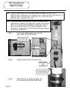
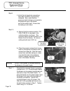
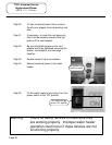
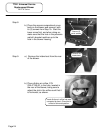
Step 8.
b.) Place the access compartment cover
back on the blower and secure it with
its (3) screws from Step 7a. Start the
lower screw first, and when doing so,
make sure that the hole in the pressure
switch’s bracket matches up to the
hole in the blower housing.
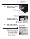
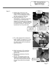
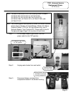
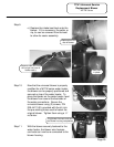
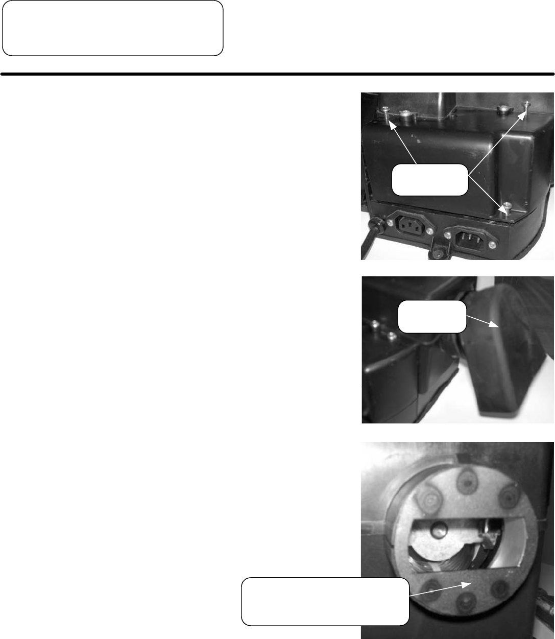
Step 9. a.) Remove the intake boot from the rear
of the blower.
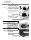
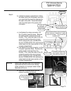
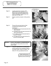
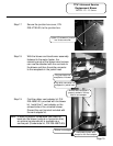
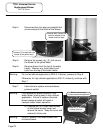
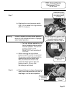
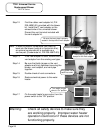
b.) Place dilution air orifice, P/N
239-47190-00, in the hole, located in
the rear of the blower, being sure to
adjust the slot in the orifice such that it
is horizontal, as shown.
TTW1 Universal Service
Replacement Blower
M1TW Series
Page 24
Secure (3)
cover screws.
Remove air
intake boot.
Insert dilution air orifice into area
concealed by boot. Orient slot in
orifice to horizontal position.