


31
4. Turn power on (after completing electrical connections – refer to Section VIII, “Electrical
Connections”) and fully open a hot water tap.
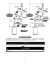
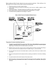
5. Measure the gas pressures to see that these are within the specified limits below:
Supply Pressure: Nat. Gas: Min.: 6”, Max.: 10.5”
L.P. Gas: Min.: 10”, Max: 13.5” w.c.
Manifold Pressure: Nat. Gas: 3.7” w.c. High Fire, 0.8” w.c. Low Fire
L.P. Gas: 4.2” w.c. High Fire, 0.9” w.c. Low Fire
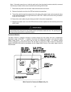
6. Turn off the hot water faucets. Disconnect the electrical power to the water heater. Remove the
pressure gauges and replace the plugs. Check for gas leaks around the plugs.
7. Replace the front control panel. Restore electrical power to the water heater
NOTICE
If the gas supply pressure is below the specified value, check the gas piping to insure that it is the correct
size for all the gas appliances on line. Check the supply pressure with all the gas appliances in operation.
The manifold pressure will vary with the water flow rate. Several hot water faucets may need to be
opened with the temperature control set on the highest setting in order to get maximum high fire manifold
pressure. If the manifold pressure is below the specified value and there is sufficient water pressure and
flow, be sure the inlet gas pressure is within the specified limits before attempting to adjust the manifold
pressure.