


7
TEMPERATURE AND PRESSURE RELIEF VALVE –
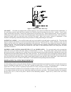
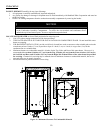
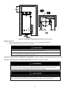
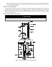
CONDENSATE DRAIN - The water heater should either be raised several inches above the floor on a concrete slab or use a low
profile condensate pump to allow free drainage of condensate from the elbow drain fitting. This water heater is a condensing type unit
and requires a drain to be located in close proximity to allow the condensate to drain safely. The condensate drains from the unit at
the exhaust elbow located near the bottom of the unit. Using an approved primer and cement (refer to “Venting” section), connect a
3/4" elbow or 3/4" coupling over the outside of the drain outlet and use 3/4" pipe for the drain trap and condensate line to a drain.
Make sure the condensate drain line slopes down, away from the water heater at least 1/8" per foot toward the drain. The condensate
drain pipe must not be routed through an area subject to below freezing temperatures. The condensate build-up will block the exhaust
outlet, which will cause improper operation. Refer to Figure 2 for the proper connection of an elbow to the drain outlet and a
condensate trap.
Keep clear of the combination temperature and pressure relief valve discharge line outlet. The
discharge may be hot enough to cause scald injury. The water is under pressure and may splash.
For protection against excessive temperatures and pressure, install temperature and pressure
protective equipment required by local codes, but not less than a combination temperature and
pressure relief valve certified by a nationally recognized testing laboratory that maintains
periodic inspection of production of listed equipment or materials as meeting the requirements of
the Standard for Relief Valves and Automatic Gas Shutoff Devices for Hot Water Supply
Systems, ANSI Z21.22 and the Standard CAN1-4.4 Temperature, Pressure, Temperature and
Pressure Relief Valves and Vacuum Relief Valves. The combination temperature and pressure
relief valve must be marked with a maximum set pressure not to exceed the maximum working
pressure of the water heater. The combination temperature and pressure relief valve rating
must not be less than the hourly rating of the water heater
Install the combination temperature and pressure relief valve into the opening provided and
marked for this purpose on the water heater.
Note: Some models may already be equipped or supplied with an installed combination
temperature and pressure relief valve. Verify that the combination temperature and pressure
relief valve complies with local codes. If the combination temperature and pressure relief valve
does not comply with local codes, replace it with one that does. Follow the installation
instructions above on this page
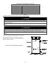
Install a discharge line so that water discharged from the combination temperature and pressure
relief valve will exit within 6 inches (15.2 cm) above, or any distance below the structural floor
and cannot contact any live electrical part. The discharge line is to be installed to allow for
complete drainage of both the combination temperature and pressure relief valve and the
discharge line. The discharge opening must not be subjected to blockage or freezing. DO NOT
thread, plug or cap the discharge line. It is recommended that a minimum clearance of 4 inches
(10.2 cm) be provided on the side of the water heater for servicing and maintenance of the
combination temperature and pressure relief valve.
Do not place a valve between the combination temperature and pressure relief valve and the
tank!
WARNING