


48
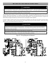
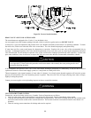
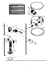
CC Ignition Control Ass'y
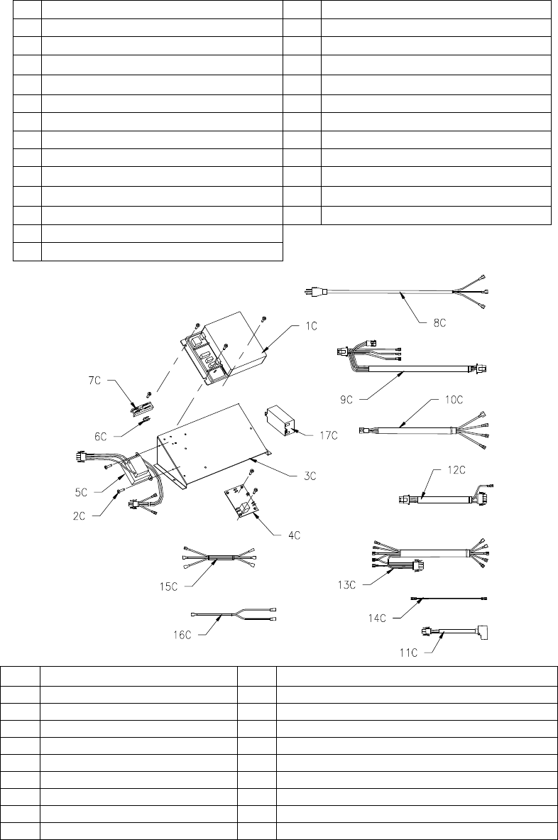
1C Electronics Control Module 10C Thermostat Wire Harness
2C Screw #8-32 x ½ 11C Rectifier Harness (Specify model)
3C Control Mounting Panel 12C Blower Wire Harness (Specify model)
4C Thermostat PC Board 13C Power Switch Wire Harness
5C Transformer – 120/24 VAC 14C Flame Sensor Wire Harness
6C Terminal 15C Powered Anode Control Harness (399 only)
7C Terminal Strip 16C Powered Anode Harness (399 only)
8C Power Cord 17C Powered Anode Control (399 only)
9C Controller Wire Harness
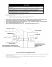
Customer must specify complete model number and serial number when ordering service parts.
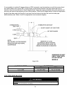
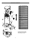
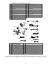
2 Combustion Ass'y (pictured previous page)
1A Combustion Ass’y (Specify model) 15A Gasket Blower Transition (Specify model)
2A Blower/Gas Valve Ass’y (Specify model) 16A Screw 8 -32 x ¼ RHCR
3A Burner Ass’y (Specify model) 17A Gasket Flame Sensor
4A Blower – EBM (Specify model) 18A Flame Sensor
5A Silicone Hose 19A Transition Tube
6A Burner Mounting Insert Gasket 20A Nut Hex Washer
7A Screw 10-32 x ¾ SHCS 21A Gasket Hot Surface Ignitor
8A Gasket & Screw 22A Hot Surface Ignitor
9A Gas Valve (Specify model) 23A Burner Mounting Gasket
10A Nipple 1/2 NPT x 3" 24A Burner 21 Port
11A Reducer ¾ x 1/2 NPT (or ¾” x 1” for 399) 25A Burner Mounting Gasket
12A Nipple ¾ NPT x 6" (or 1” NPT for 399) 26A Burner Mounting Insert
13A 2" dia. Flex Reducer (or PVC reducer for 399)
14A Inlet (PVC)