


19
CAUTION
The vent shall terminate a minimum of 12 inches (30.5 cm) above expected snowfall level to prevent blockage of vent termination.
The horizontal centerline of the exhaust vent terminal (if applicable) must not be located lower than the horizontal centerline of the
air intake terminal if vented through the same wall.
A service drain loop must be installed in the drain tubing to serve as a condensate trap to prevent flue gases from escaping into the
room.
DO NOT position the air intake above the exhaust terminal.
NEVER locate the air intake where exhaust gases can be introduced.
All vent pipes and terminals are to have a 1” minimum clearance to combustibles. DO NOT use the placement of insulation or other
materials in the required clearance spaces surrounding the venting to combustible materials unless otherwise specified.
VENTING
The venting instructions must be followed to avoid restricted combustion or recirculation of flue gases. Such conditions cause
sooting or risks of fire and asphyxiation.
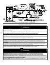
This water heater can be installed as either a direct vent system or power vent (air from inside) system. If it is installed as a
direct vent system, then the air intake and the exhaust vent are piped to the outside. If a power vented system is used, then air is
drawn from inside and only the exhaust is piped to the outside. Determine which system is best for your application and install
as described in the following sections.
DIRECT VENT INSTALLATION
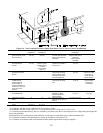
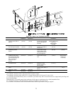
Venting may be run horizontally through an outside wall or vertically through a roof through using either 3 inch (7.6 cm) or 4
inch (10.2 cm) diameter PVC, ABS or CPVC pipe. This water heater is supplied with a screened intake elbow and exhaust
coupling referred to as the air intake terminal and the exhaust vent terminal.
NOTICE
If 4 inch (10.2 cm) PVC, ABS, or CPVC pipe is used, then a use a 4 inch (10.2 cm) to 3 inch (7.6 cm) reducer fitting before exiting
the wall or roof to use the supplied screened intake and exhaust terminals.
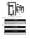
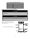
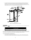
Direct Vent Terminal Location
Plan the vent system layout so that proper clearances are maintained from plumbing and wiring. Before the vent is installed,
determine the vent pipe termination location as shown in Figure 12.
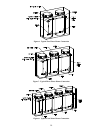
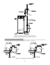
NOTICE
The air intake and exhaust terminals may be located on separate outside walls or one terminal may exit the roof while the other is
through the wall. The total combined equivalent vent length must be within the limits specified in the venting tables and the intake
length cannot exceed the exhaust by more than 30 feet (9 m). The minimum recommended vent separation distance between the
intake and exhaust terminals is 36 inches (91.4 cm). Local conditions may require a need for greater vent separation distances.
CAUTION
Check to make sure flue gases do not recirculate into the air intake terminal when using direct venting. If the water heater is having
service issues, flue recirculation may be a contributing factor. Even when the minimum vent terminal separation distances are
followed, recirculation may still occur depending upon the location outside the building, the distance from other buildings, proximity to
corners, weather conditions, wind patterns, and snow depth. Periodically check to make sure that flue recirculation is not occurring.
Signs of flue gas recirculation include frosted or frozen intake terminals, condensate in the intake terminal and venting system,
oxidation or white chalk material on the flame sensor or igniter shield. Correction to flue recirculation may involve angling the intake
away from the exhaust terminal, increasing the distance between them, relocating the air intake to another side of the building, or
using inside air for combustion. Check to be sure the intake and exhaust terminals are not obstructed, especially during periods of
below freezing weather.
All intake and exhaust venting components must have the same diameter size. Do not use a different size on the intake and
exhaust venting. For 4 inch (10.2 cm) venting, use the supplied 3 inch (7.6 cm) vent terminals.
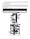
Be sure the condensate runs freely to a drain and does not accumulate inside the water heater. In cold climates, precautions may
need to be taken to insure that the condensate drain does not freeze. Make sure the condensate trap or drain loop is installed to
prevent flue gases from being discharged into the room. Refer to the Venting section of the Installation and Operating Instructions
Manual for complete instructions on venting and condensate drainage.