


12
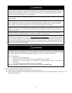
DANGER
Temperature setting should not exceed safe temperature at fixtures. See Approximate
Time/Temperature Scald Chart in “Section V: Water Connections”. If higher preheat temperatures are
necessary to obtain adequate booster output, add an anti-scald valve for hot water supplied to fixtures.
LOCATION
KEEP APPLIANCE AREA CLEAR AND FREE OF COMBUSTIBLE MATERIALS, GASOLINE AND OTHER
FLAMMABLE VAPORS AND LIQUIDS.
This water heater must be located in an area where the general public does not have access to set temperatures.
AIR REQUIREMENTS
1. Do not obstruct the flow of combustion and ventilating air.
2. For safe operation, adequate air is needed for combustion and ventilation. Sooting may result in serious damage to the water
heater and risk of fire or explosion. It can also create a risk of asphyxiation. Such a condition often will result in a yellow,
luminous burner flame, causing carboning or sooting of the combustion chamber, burner and flue tubes.
MECHANICAL EXHAUSTING OF ROOM AIR
1. Where an exhaust fan is installed in the same room with this water heater and combustion air is drawn from inside the
room, sufficient openings for air must be provided in the walls. UNDERSIZED OPENINGS WILL CAUSE AIR TO BE
DRAWN INTO THE ROOM THROUGH THE WATER HEATER’S VENTING SYSTEM, CAUSING POOR
COMBUSTION THAT MAY BE HAZARDOUS TO LIFE. SOOTING MAY RESULT IN SERIOUS DAMAGE TO
THE WATER HEATER AND RISK OF FIRE OR EXPLOSION, WHICH CAN ALSO CREATE A RISK OF
ASPHYXIATION. Refer to local codes and /or National Fuel Gas Code for proper air opening sizing.
UNCONFINED SPACE
1. In buildings of conventional frame, brick or stone construction, unconfined spaces may provide adequate air for combustion
and ventilation.
2. If the unconfined space is within a building of tight construction (buildings using the following construction: weather
stripping, heavy insulation, caulking, vapor barrier, etc.), air for combustion and ventilation must be obtained from outdoors.
This may be accomplished by piping air directly to the water heater from outside or providing opening or ducts in the wall.
The installation instructions for confined spaces in tightly constructed buildings must be followed to ensure adequate air
supply.
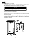
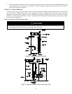
CONFINED SPACE
1. When drawing combustion air from inside a conventionally constructed building to a confined space, such a space shall be
provided with two permanent openings.
The top opening is to be located within 12 inches (30.5 cm) of the enclosure top and the bottom opening within 12
inches (30.5 cm) of the enclosure bottom.
Each opening shall have a free area of at least 1 inch² (6.5 cm²) per 1000 Btu/h (.3 kw) of the total input of all
appliances in the enclosure, but not less than 100 inches² (645.2 cm²).
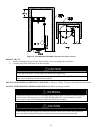
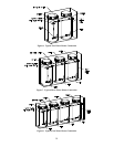
2. If the confined space is within a building of tight construction, air for combustion and ventilation must be obtained from
outdoors. This may be accomplished by piping air directly to the water heater from outside or providing opening or ducts
in the wall. When directly communicating with the outdoors through vertical ducts, two permanent openings, located in the
above manner, shall be provided.
Each opening shall have a free area of not less than 1 inch² (6.5 cm²) per 4000 Btu/h (1.2 kw) of the total input of all
appliances in the enclosure.
If horizontal ducts are used, each opening shall have a free area of not less than 1 inch² (6.5 cm²) per 2000 Btu/h (.6
kw) of the total input of all appliances in the enclosure.