


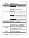

Specifications
Power Supply
Current Draw
Gas Supply Connection
Approved Gas Type
Gas Pressure (Nat. & L.P.)
Venting System
Minimum Clearance for Servicing
Maximum Water Supply Pressure
Thermostat Sensor(s)
Control Board
Control Display
Transformer
Pilot
Induced Draft Blower
Dedicated 120 VAC, 60 Hz., 15 A
Less than 5 Amps
PDV-S & PDV-T MODELS: 3/4" NPT Minimum connection to gas valve.
INDUCED DRAFT MODELS: 1" NPT Minimum conncection to gas valve.
Schedule 40 black iron pipe recommended for all models.
Natural or Propane. Gas supply must match the gas type listed on the
water heater rating label.
Manifold Pressure: 4.5" w.c. natural gas, 10.0" w.c. L.P.
Gas Supply Pressure: At least 1" above manifold pressure with water heater
operating, 14" w.c. maximum
PDV-S MODELS:
Power vented through either 3" or 4" diameter PVC, CPVC, or ABS pipe for
150,000 or 199,999 Btu/hr. models, 4" only for 250,000 Btu/hr. models.
Refer to the installation instruction manual for further information on venting
lengths and installation requirements.
PDV-T MODELS:
Power vented through Co-axial Venting (pipe inside a pipe) - Combustion air
enters from the outside the building through an outer pipe (200mm diam.)
and exhausts flue products through the inside pipe (130mm diam.). Refer to
the installation instruction manual for further information on venting lengths
and installation requirements.
INDUCED DRAFT MODELS:
Connect 8” vent to blower vent collar for venting through a chimney or type
B vent only. Vertical venting only.
30" Front Clearance, 16" Top, 2" Sides and Rear
150 PSI
Redundant thermister with 11,900 + or - 0.5% ohms resistance at 70 deg. F.
Sensor inside well for lower sensor. PDV-T model series and Induced Draft
models also use an upper sensor (dual sensors for these models).
Honeywell Integrated Control Board for Temperature Control, Induced Draft
Blower, and Ignition Control Functions. Operates on 24 volts AC current
from transformer. Single sensor boards for PDV-S models and dual sensor
boards for PDV-T models and Induced Draft models.
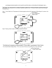
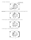
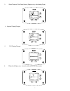
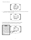
Honeywell LCD Control Display with Temperature Setpoint, Format, and
Error Code Display in User Mode, Diagnostic Functions in Service Mode.
Communicates with Control Board. 24 volts AC. Same control display used
on all models.
120 VAC Primary, 24 VAC Secondary, 40 VA
Intermittent Pilot with Spark Electrode and Flame Sensor monitored by
Control Board
PDV-S MODELS: 115 VAC, 60 Hz., 4.3 Amps.
PDV-T MODELS AND D80T725, D65T625: 115 VAC, 60 Hz., 3.6 Amps.
5