


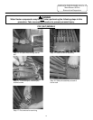

SERVICE PROCEDURE PDV24-IV
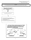
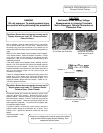
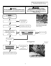
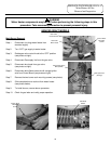
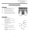
Main Burner Operation Testing
CAUTION
Be Careful When Making Voltage
Measurements or Jumping Terminals
Not to Damage or Deform Connectors or
Connector Pins.
DANGER
120 volt exposure. To avoid personal injury,
use caution while performing this procedure.
Condition:
Main burner will not light,
Display shows “Heating” under temperature
setpoint.
Tank is cold.
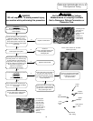
Is Pilot lit?
See “pilot will not light”
in “Pilot Operation
Testing” section.
Does control board continue to spark with
pilot lit?
See “Pilot lights, no flame signal” in
“Pilot Operation Testing” section.
Disconnect control wire harness from
“Control” plug of control board.
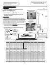
Is there 22-27 volts AC across
pin terminals 5 & 8? Refer to wiring
diagram
(also see photo )
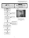
Disconnect brown wire lead from
“MV” terminal of gas valve.
Is there 22-27 volts AC across
brown wire lead & ground
Replace control board.
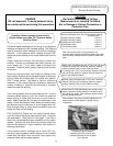
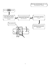
Be sure control display is showing “Heating”,
pilot is lit and control is not sparking.
Recheck voltage across control board
pin terminals 5 & 8 ((MV & MV/PV)
Is voltage present?
Check wire harness for damage or loose
connections. Repair or replace as needed.
Check incoming gas
pressure to gas valve. if
okay,
replace gas valve.
Reconnect control plug
to control board.
N
Y
NN
Y
N
Y
Y
N
Y
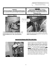
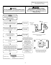
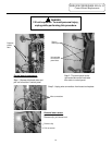
Checking MV & MV/PV control plug
pins to gas valve for 24 volts output
during heating cycle (pilot must be
lit with no sparking).
Brown wire disconnected
from “MV” terminal of gas
valve
Ground lug of
gas valve
Checking main valve (MV) voltage to gas valve.
33