


SERVICE PROCEDURE PDV23-II
Pressure Switch Testing
DANGER
120 volt exposure. To avoid personal injury,
use caution while performing this procedure.
CAUTION
Be Careful When Making Voltage
Measurements or Jumping Terminals
Not to Damage or Deform Connectors or
Connector Pins.
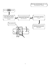
Condition: Blower operates, burners not lit.
Display shows error code “29” (Pressure Switch
Failed to Close).
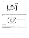
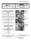
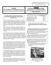
Connect a digital manometer to the tubing for the pressure
switches and determine the average reading. See table at
right for pressure switch settings and minimum readings
required. Is the pressure switch reading at least 0.20"
above the switch reading for the model tested (see chart at
right)?
Note: During normal hot running conditions, the
pressure switch readings should be at least 0.20" higher
than the above readings where the pressure switch will
open.
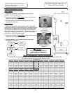
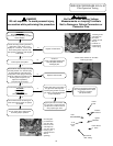
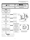
Check the total equivalent vent length by adding up the
total number of elbows and the straight lengths of vent pipe
for the intake and exhaust pipe (or coaxial vent pipe for
PDV-T model series). See table at right for maximum
distances. If the venting distance is excessive, reduce the
number of elbows or route the vent terminals to a shorter
distance outside the building.
See installation instruction manuals supplied with the
water heater for further details on proper venting
installations.
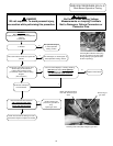
If the venting system and vent terminals are O.K., but the
pressure switch reading is still low, check the pressure
switch tubing to make sure there are no small holes or
kinks. Make sure there are no drops of condensate in the
tubing. Check the pressure switch tubing connection fitting
and pressure tap to make sure it is not clogged with dirt.
Blow through tubing to verify that the pressure taps and
tubing are clear and not leaking.
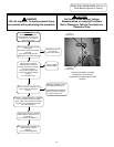
If the pressure switch readings are at least 0.20" w.c.
above the above pressure switch settings for the installed
model and the switch does not close, then replace the
pressure switch with the same setpoint.
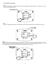
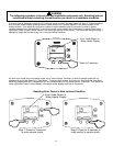
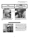
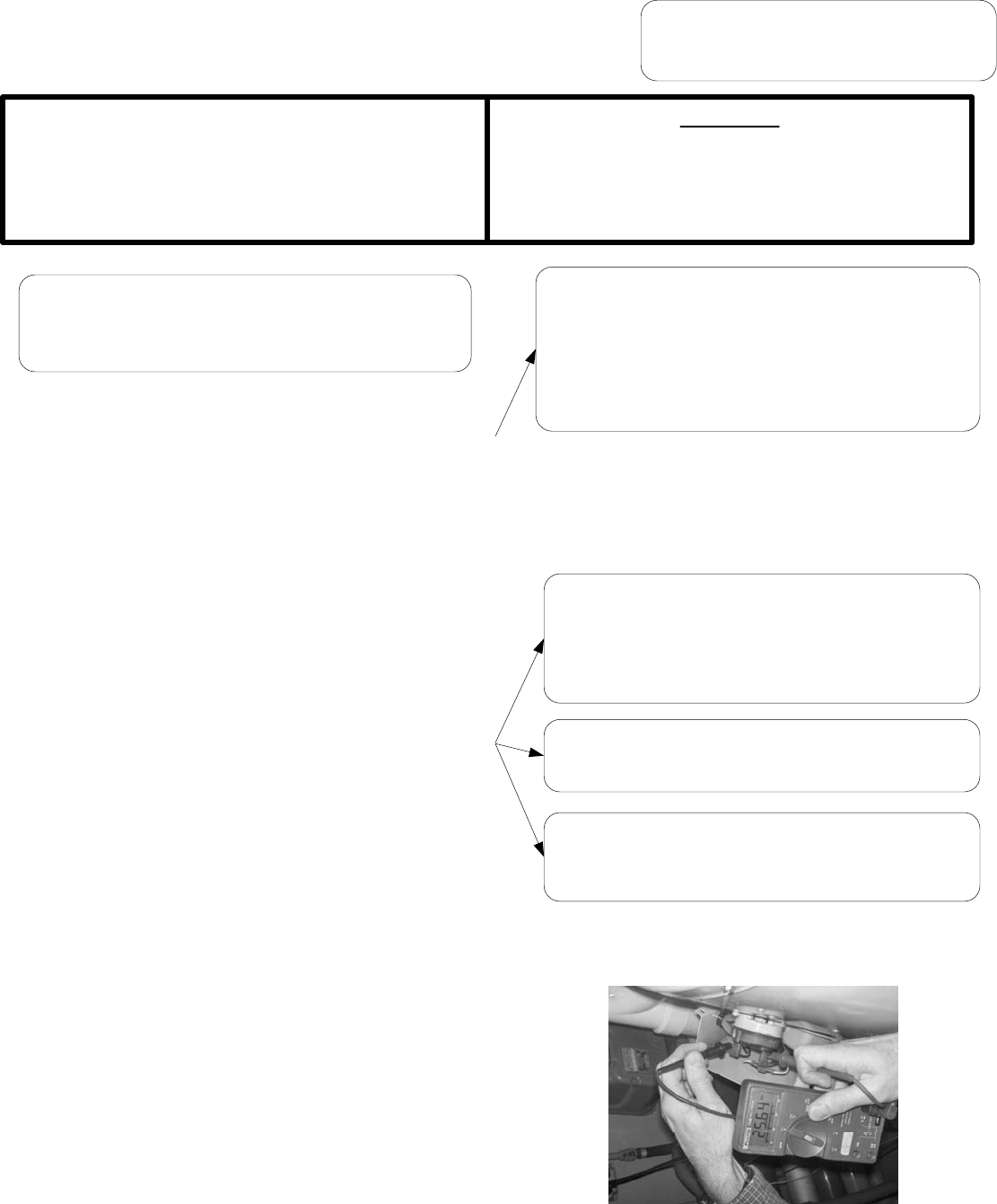
Checking pressure switch contacts.
Contacts are open if blower is
operating and there is 22-26 volts
measured between the two contacts
(as in photos)
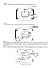
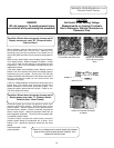
PDV-S MODELS: Check the vent safety thermal switch
near the outlet of the blower (see photo at right). Press the
red reset button. (See photo on next page). If you feel a
slight click, the temperature was excessive and the switch
opened. Check to be sure the burner access screws are
tight and the gasket is in good condition (see section on
servicing the burners)
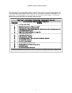
PDV80,100S-150,200 Models with 3" PVC vent: Maximum
Distance of 40 feet with one 90 deg. elbow for intake or
exhaust (subtract 5 feet for each additional elbow).
For venting with 4" PVC vent: Maximum distance of 55 feet
with one 90 deg. elbow for intake or exhaust (subtract 5
feet for each additional elbow).
PDV80S,100S-250 Models with 4" PVC vent: Maximum
distance of 55 feet with one 90 deg. elbow for intake or
exhaust (subtract 5 feet for each additional elbow).
PDV80T300, PDV100T360 Models with coaxial venting
system: Maximum venting distance of 19 feet 6 inches
with one 90 deg. elbow. Each additional elbow reduces
the venting distance by 39".
Minimum Differential Dual Tap Pressure Switch Settings:
(Contacts open)
PDV80S,100S-150 models: -2.00" w.c.
PDV80S,100S-200 models: -1.20" w.c.
PDV80S,100S-250 models: -2.00" w.c.
PDV80T300 models: -1.20" w.c.
PDV100T360 models: -0.60" w.c.
27
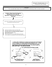
Check intake and exhaust vent terminals outside the
building. Is there any blockage from debris (leaves, ice,
snow, paper, etc.). If so, clear intake or exhaust vent
terminals. Pressure switch should close and the burners
should fire.