


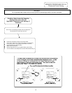
SERVICE PROCEDURE PDV24-II
Pressure Switch Testing
DANGER
120 volt exposure. To avoid personal injury,
use caution while performing this procedure.
CAUTION
Be Careful When Making Voltage
Measurements or Jumping Terminals
Not to Damage or Deform Connectors or
Connector Pins.
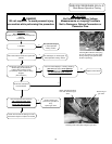
Condition: Blower does not operate, burners not lit.
Display shows error code “2” (Pressure Switch
Failed to Open - Stuck Closed).
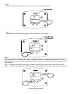
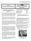
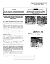
Disconnect power and remove the pressure switch cover
(previous photo-PDV models). Disconnect wires on the
pressure switch. Measure continuity on the pressure switch
terminals with an ohmeter. If there is continuity, the pressure
switch is stuck closed. Make sure pressure switch has not
been bypassed (jumpered). The control will not operate with
a jumpered pressure switch.
If pressure switch contacts are stuck closed, check the
pressure switch tubing for condensate, dirt, or kinks. If the
tubing is O.K., replace the pressure switch with the same
setting.
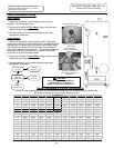
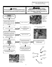
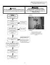
Condition: Blower does not operate, burners not lit.
Display shows error code “29” (Pressure Switch
Failed to Close ).
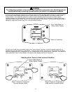
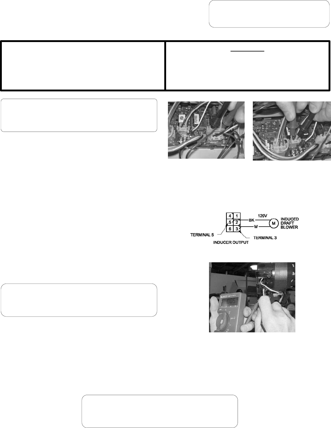
With a voltmeter, check to make sure the “line in” connection
to the control board has 110-120 volts. Make sure the
secondary plug from the transformer to the board has 24
volts at the yellow and blue wire pin terminals (see photos to
right).
Reconnect power. Verify
proper operation.
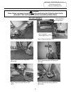
Make sure the water heater control display shows “Heating”
in the status window. Raise the setpoint if needed. If there
is no call for heat and the setpoint is well above the tank
temperature, refer to the thermostat troubleshooting and
replacement section.
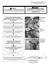
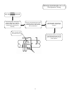
If the water heater control display shows “Heating” and the
blower is off, Error code 29, then check the voltage output at
the blower plug on the board. Should read 110-120 volts
between the black and white wires to the blower (terminals 5
and 3 on the inducer output on the control board, see
illustration to the right).
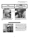
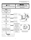
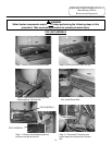
If there is voltage between the black and white wires to the
blower plug on the board, then check the voltage at the
blower connection on the blower (see photo at right). If no
voltage is present, replace the wire harness. If there is 110-
120 volts, replace the blower.
Checking line voltage to board.
Pins to black and white wires.
Checking secondary
voltage from transformer.
Pins to blue and yellow
wires.
Checking line voltage at the
blower wire harness connection
on blower.
If there is no voltage on the control board to the blower
plug and the control display shows “Heating”, then
replace the control board.
29