


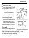
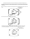
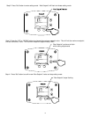

1 Thermostat calls for heat:
.
The relay closes on the control board, sending line voltage (115-120 volts) from “inducer” terminals #5 and 3 on the
control board to the induced draft blower.
2
The blower starts and when sufficient vacuum is achieved, the pressure switch closes and completes the 24 volt
circuit between terminals 1 and 3 on the Control Plug to the the board, allowing the ignition sequence to proceed.
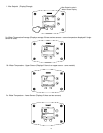
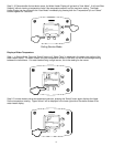
The blower “purges” any remaining combustion products from the previous cycle for 15 seconds before allowing the
pilot to light. This is the pre-purge period of the ignition cycle.
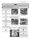
3
4
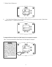
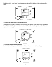
Once pilot flame is proven, sparking will stop.
Sequence of Operation
Trial for ignition (three 90 second ignition trials, with 75
second pauses between trials).
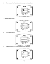
Control Board simultaneously sends:
1. 24 volts from control pin terminal #8, to “MV/PV”
terminal of gas valve (common terminal).
2. 24 volts from control pin terminal #2, to “PV”
terminal of gas valve to establish
gas flow at pilot.
3. Low current high voltage from “spark”
terminal, to generate spark at the pilot and
ignite pilot gas flow.
4. Pilot flame proving signal (measured in
micro-amps). from the “sense” terminal, to
prove pilot flame.
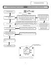
5
Once sparking stops, 24 volts is sent from control pin
terminal #5 on control board, to “MV” terminal on gas valve
to establish main burner gas flow. Main burners ignite from
the pilot flame.
The control board constantly monitors pilot flame through
the flame sensor rod. If pilot flame is lost, pilot and main
burners are shut down. After a 75 second inter-purge
period, the control will attempt to re-light the pilot beginning
at sequence 3 above.
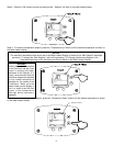
7
Main burner fires until the thermostat is satisfied. The control
board interrupts 24 volts through the gas valve circuit. Pilot
and main burners are turned off.
8
The induced draft blower shuts off 5 seconds after the
gas valve closes. This is the post-purge period.
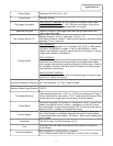
WIRING DIAGRAM
LOCKOUT CONDITION
Control board will go into “Soft Lockout” if the pilot cannot be lit
after 3 ignition trials. The water heater display indicates a lockout
condition by showing an error code number (62 or 63) with
“Service Needed” in the display window. Refer to error codes in the
diagnostic section of this Service Manual. In a “Soft Lockout” condition,
the control will wait for 60 minutes and then make 2 more attempts to light the pilot and establish the main burners.
Soft lockout reset is accomplished by depressing the lower right button under “Reset” for 3 seconds.
If the water heater should reach 200 degrees F, then the high limit control will shut off the burners and the water heater will
go into a “Hard Lockout”. Error code 65 will be shown in the water heater display. The control can only be reset in the
“service mode”, which is detailed in the next section of this Service Manual.
If the exhaust or intake terminals become blocked during operation or if the blower motor fails, the pressure switch will open
and error code 29 will appear in the display. When the condition is corrected, the error code will disappear and the water
heater will resume normal operation. No resetting of the control display is needed for the pressure switch error code.
6