


SERVICE PROCEDURE PDV24-II
Pressure Switch Testing
DANGER
120 volt exposure. To avoid personal injury,
use caution while performing this procedure.
CAUTION
Be Careful When Making Voltage
Measurements or Jumping Terminals
Not to Damage or Deform Connectors or
Connector Pins.
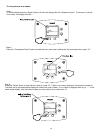
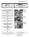
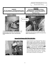
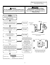
Vent safety thermal switch on PDV-S blower. Depress red
reset button in center of switch. If a slight click is felt, switch
opened. Check for loose or leaking burner access panel (see
section on servicing burners)
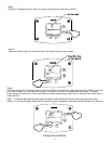
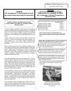
Check pressure switch tubing to the pressure switch. Make
sure tubing does not have kinks, holes, condensate, or dirt
blocking air pressure to the switch. The tubing to the
blower tap attaches to the - (minus) tap on the pressure
switch.
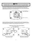
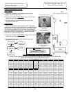
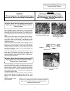
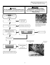
Induced Draft Models use a single tap pressure switch to
measure vacuum in the flue collector. The pressure
switch is located inside the control box (see photo to left).
Connect a digital manometer to a tee in the pressure
switch tubing and measure the vacuum with the blower
operating. The vacuum should be in the range of -1.70"
to -2.10" w.c. The pressure switch contacts will open at
-1.25" and close by -1.40" w.c. If the vacuum is below -
1.50", check to make sure the flue damper is fully open
when the blower is operating. Make sure the damper and
rod are not binding. Make sure there are no restrictions
in the venting system and that is at least 8" in diameter.
Venting is for vertical gravity venting only. Insure that
there is sufficient combustion air to the utility room.
Induced Draft Models (D80T725 & D65T625):
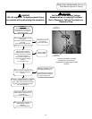
Red reset button
28
PDV(S & T) Models Vent Safety Switch (PDV-S Models Only)