


INSTALLATION
Form No. EBOOSTERBWM-1009
6
General
For the most effective operation, install the booster water heater
as close as possible to the commercial dish machine. The
location must have a solid foundation or strong table/counter
construction along with being clean and dry. Adequate front
clearance is required to allow for accessibility to the control
compartment. Location must have adequate clearance to allow
for inspection, testing, or replacement of temperature/pressure
relief valve.
ELECTRIC SHOCK HAZARD:
• This unit must be installed by qualified, trained
installers. Installation must conform to all local
electrical and plumbing codes. Check with your local
plumbing and electrical inspectors for proper
procedures and codes.
• Consult a licensed electrical contractor for proper
electrical installation conforming to local electrical
codes and the National Electrical Code (N.E.C.).
• Unit is not weatherproof. Locate unit indoors where
ambient air temperature is a minimum of 70°F (21°C).
• Do not place aftermarket covers on or over booster
water heater. Doing so can cause temperature and
moisture build-up resulting in premature failure and
electrical shock.
Install booster water heater as close as possible to the
commercial dishwasher. Employ recirculation if distance
between booster and commercial dishwasher exceeds
National Sanitation Foundation (NSF) specifications of
five (5) linear feet (1524 mm).
Install booster water heater in horizontal position with
base parallel to the floor and inlet connection at the lowest
point. If installing with legs, mount on floor. If installing
with slide brackets, mount under dish table. DO NOT
mount on walls or in ceiling. Unit must be accessible for
service. Improper installation could create an unsafe
condition.
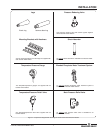
Booster Heaters are shipped with most components pre-
assembled. Care should be taken when unpacking shipping
carton to avoid damage to unit and components enclosed.
Components are shipped with the heater unit (see Figure 4).
1. Remove the unit from the carton.
2. Remove the information packet.
3. Remove tape and protective packaging from all surfaces
of unit.
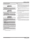
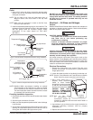
4. If the unit is equipped with legs, carefully lay the unit on its
side and install the four legs as shown in Figure 2.
Do not lay unit on the side with the control panel. Damage
to the unit could occur.
NOTICE
WARNING
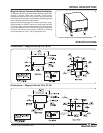
Figure 2. Installing the Legs
NOTE: If unit is not level, use an adjustable open-end wrench
to adjust the foot of each leg until unit is level. Each leg
is adjustable from 6″ (152 mm) to 7″ (178 mm).
5. If installing the unit with mounting brackets, use the
following procedure:
Make sure the dish table is strong enough to support the
weight of the booster heater and water when installing
with slide mounting brackets.
Follow standard welding safety and operational
procedures when attaching sliderails to bottom of dish
table.
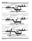
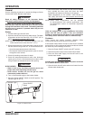
• Space slide rails as shown below, and weld the rails to
the bottom of the dish table.
Figure 3. Attaching the Slide Rails to the Dish Table
• Using the Bradford White slide brackets as a template,
drill 1/8″ (3 mm) holes into the sides of the heater jacket.
• Attach slide brackets
to the sides of the
booster water heater
with 3/4 x 8 sheet
metal screws
supplied.
• Slide the booster
water heater onto
slide rails under dish
table.
WARNING
Models 24–58 kW
20-1/4″
(514 mm)
Weld slide rail
to bottom of
dish table.
Models 6–18 kW
15-1/4″
(387 mm)
Fasten slide brackets
to booster water heater
sides.