


INSTALLATION
Form No. EBOOSTERBWM-1009
11
DO NOT turn on power to the booster water heater until
tank has been filled with water and all air has been vented
through dish machine rinse nozzle. The heating elements
will burn out in seconds if operated when they are not
immersed in water.
Electrical — All Sizes and Voltages
General
Bradford White Electric Booster Water Heaters are available for
operation on standard power systems. Check the identification
decal for the proper power supply.
ELECTRIC SHOCK HAZARD:
• Turn power OFF at disconnect switch/circuit breaker
and allow unit to cool before performing any
maintenance or cleaning.
• Consult a licensed electrical contractor for proper
electrical installation conforming to local electrical
codes and the National Electrical Code (N.E.C.).
Connect electric booster water heater to the same power
supply as indicated on the specification decal only. Units
connected to an incorrect power supply voids the product
warranty and will damage the equipment.
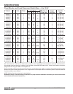
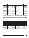
All internal electrical connections have been made at the
factory. See the “Circuit Breaker and Fused Disconnect Switch
Sizes” charts in the SPECIFICATIONS section for supply wire
size, fuse, breaker, and conduit recommendations. Consult local
codes for verification and compliance.
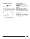
Electrical Connections
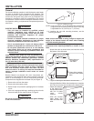
1. Remove the front jacket cover screws. Ease the cover
forward and upward. The control box is under the front
hinged jacket cover.
2. Locate the heater terminal or fuse block(s) inside the unit.
NOTE: See the “Circuit Breaker and Fused Disconnect Switch
Sizes” charts for proper connections and wire size.
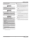
3. Bring power leads from a
properly sized disconnect
switch or circuit breaker
through the knockout provided
on the unit, and connect to the
terminal or fuse block(s). USE
COPPER WIRE ONLY.
TIGHTEN CONNECTIONS
PROPERLY TO A MINIMUM
OF 40 INCH POUNDS.
NOTE: Due to the rigors
of transportation all
connections should be
checked for tightness before booster water heater is
put into operation.
4. A grounding lug is provided near the supply terminals. An
equipment grounding conductor must be properly
connected to it.
5. Replace and secure the front jacket cover.
Knockout
Locations
NOTICE
WARNING
CAUTION
Outlet
1. Using a 3/4″ union and piping, connect the booster water
heater outlet to the commercial dish machine sanitizing
rinse pipe connection.
NOTE: The red mark on the inlet and outlet water pipes of
Magnum Series units must remain in the top most
position.
NOTE: Make sure the connection is made to the final rinse
and not to the wash tank.
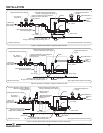
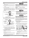
2. Install a temperature/pressure gauge in the outlet line. The
temperature sensing element must be in the water stream
and the gauge must be mounted upright. Water
temperature at the outlet should be 185°–190°F
(85°–88°C).
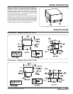
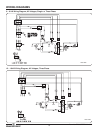
Figure 8. Recommended Temperature/Pressure Gauge Installation
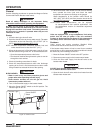
Figure 9. Alternate Temperature/Pressure Gauge Installation
NOTE: Bradford White recommends installing an optional
shock absorber in the outlet line as close as possible
to the commercial dish machine solenoid rinse valve.
The shock absorber softens the water hammer caused
by automatic dish machine valves.
Plumbing Installation Inspection
1. Close drain pipe shut-off valve and fill booster water heater
with water.
2. Check all pipe connections for leaks.
3. Make sure the temperature/pressurerelief valve discharge
is not blocked.
4. Vent air from the booster tank before turning on the unit by
opening the temperature/pressure relief valve as well as
running the dish machine through several cycles.
Temperature/
Pressure Gauge
w/1/2″ pipe thread
1/2″ Copper
Female Fitting
Adapter
Temperature
Sensing
Element
Bottom of sensor
centered in
copper pipe.
3/4″ Nominal
Copper Pipe
3/4″ Copper Tee
Temperature/Pressure
Gauge
3/4″ Nominal
Copper Pipe
1/2″ pipe thread
1/2″ Copper Female
Fitting Adapter
Temperature
Sensing
Element