


INSTALLATION
Form No. EBOOSTERBWM-1009
8
Temperature/Pressure Relief Valves
For protection against excessive pressures and temperatures in
the booster heater, install temperature/pressure protective
equipment required by local codes. The temperature/pressure
relief valve supplied with this booster water heater is
constructed with brass working parts and heat resistant silicone
seat discs.
Temperature/pressure protective equipment should not be
less than a combination temperature/pressure relief valve
certified by a nationally recognized testing laboratory that
maintains periodic inspection of the production of this
equipment and meets the requirements for Relief Valves
and Automatic Shutoff Devices for Hot Water Supply
Systems, ANSI Z21.22-1979. The temperature/pressure
relief valve must be marked with a minimum set pressure
not to exceed the marked hydrostatic test pressure of the
booster heater as noted on the unit specifications.
FOR INSTALLING COMBINATION TEMPERATURE/
PRESSURE RELIEF VALVES IN ACCORDANCE WITH
AMERICAN NATIONAL STD. Z21.22-1979. Combination
temperature/pressure relief valves with extension
thermostats must be installed so that the temperature-
sensing element is immersed in the water within the top 6"
(152 mm) of the tank. They must be installed either in the
hot outlet service line or directly in a tank tapping.
Combination temperature/pressure relief valves that do
not have extension elements must be mounted directly in
a tank tapping located within the top 6" (152 mm) of the
tank, and shall be adequately insulated and located so as
to assure isolation from the flue gas heat or other ambient
conditions that are not indicative of stored water
temperature. TO AVOID WATER DAMAGE OR SCALDING
DUE TO VALVE OPERATION, DRAIN PIPE MUST BE
CONNECTED TO VALVE OUTLET AND RUN TO A SAFE
PLACE OF DISPOSAL. Discharge line must be as short as
possible and be the same size as the valve discharge
connection throughout its entire length. Drain line must
pitch downward from the valve and must terminate
between 1-1/2" (38 mm) and 6" (152 mm) above the floor
drain where any discharge will be clearly visible. The drain
line shall terminate plain, not threaded, with material
serviceable for temperatures up to 250°F (121°C) or
greater. Excessive length, over 30' (9144 mm), or use of
more than four elbows can cause a restriction and reduce
the discharge capacity of the valve. No shut-off valve shall
be installed between the relief valve and tank, or in the
drain line. Valve lever must be tripped periodically to
assure that waterways are clear. This device is designated
for emergency safety relief and shall not be used as an
operating control. The valves are set to relieve at 150 psi
(1034 kPa) or when water temperature reaches 210°F
(99°C). Read tag on valve for additional information.
BURN HAZARD: Valves supplied with this booster water
heater are designed for high temperature commercial
operation. Do not substitute these valves with valves
designed for domestic water heaters.
Do not use an anti-siphon or check valves on incoming
water line.
CAUTION
WARNING
Pressure Reducing Valve
If water supply pressure to the booster water heater inlet
is over 20 psi (138 kPa) during flow, install a commercial-
grade pressure reducing valve with built-in bypass for
proper operation of dish machine rinse nozzles.
NOTE: The pressure reducing valve must be the type
equipped with a high pressure bypass like the valve
supplied with this booster water heater.
Proper operation of the commercial dish machine rinse nozzles
requires that available water pressure at the rinse nozzle be
between 15 and 25 psi (103 and 172 kPa) when the nozzle is
operated. 20 psi (138 kPa) is recommended. If water pressure
available to the booster water heater inlet is over 20 psi
(138 kPa), a pressure reducing valve must be installed in the hot
water supply line to the booster water heater and adjusted to
deliver 20 psi (138 kPa) flow pressure.
The valve supplied with the unit has a built-in high pressure
bypass that prevents excessive pressure build-up as the
booster heats up. Final adjustment is required at the time of
installation.
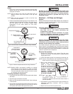
Temperature/Pressure Gauges
Bradford White requires that two temperature/pressure
gauges be installed to assure proper operation. Install one
in the supply line before the pressure reducing valve and
one in the outlet line as close to the booster water heater
as possible. This provides a visual check of the water
temperature and pressure before and after the water
heater.
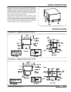
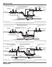
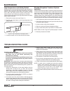
NOTE: If a check valve is installed and cannot be removed
install a back pressure relief valve set at 125 psi (862
kPa) on the incoming line between the pressure
reducing valve and the inlet to the booster water
heater. Discharge must be to open site drain (see
Figure 7).
Blended Phosphate Water Treatment
System (optional)
Bradford White recommends that the Blended Phosphate Water
Treatment System be installed with unions on the incoming 3/4"
water supply line after the pressure reducing valve and before
the booster water heater.
Cartridges supplied have a usage rating of 100,000 gallons
(378,541 liters) of water. To assure proper operation the
cartridges must be replaced when expired.
NOTE: Product failure caused by liming or sediment buildup is
not covered under warranty.
CAUTION
CAUTION