


MAINTENANCE
Form No. EBOOSTERBWM-1009
13
General
Bradford White Magnum Series Commercial Electric Booster
water heaters are designed for maximum durability and
performance, with minimum maintenance.
ELECTRIC SHOCK HAZARD:
• Turn power OFF at disconnect switch/circuit breaker
and allow unit to cool before performing any
maintenance or cleaning.
• This unit must be serviced by qualified personnel only.
Service by unqualified personnel may lead to electric
shock or burn.
• Use only Genuine Bradford White Replacement Parts
when service is required. Failure to use Genuine Bradford
White Replacement Parts will void all warranties and may
subject operators of the equipment to hazardous
electrical voltage, resulting in electrical shock or burn.
Genuine Bradford White Replacement Parts are specified
to operate safely in the environments in which they are
used. Some aftermarket or generic replacement parts do
not have the characteristics that will allow them to
operate safely in Bradford White equipment.
This unit has no “user-serviceable” parts. If service is
required on this unit, contact an Authorized Service Agent
or the Bradford White Service Department.
Thermostat Adjustment
The thermostat is factory calibrated to produce temperatures of
185°–190°F (85°–88°C). If adjustment or recalibration is
required use the following procedure.
NOTE: Low temperature dish machines require the thermostat
to be adjusted to 140°–150°F (60°–66°C).
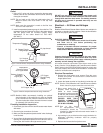
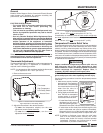
1. Remove the access cover.
Figure 11. Access Cover for Thermostat and
High Temperature Limit Safety Switch
2. Adjust the thermostat in the desired direction.
• To lower the temperature setpoint, turn the outer
adjustment screw counterclockwise.
• To raise the temperature setpoint, turn the outer
adjustment screw clockwise.
Access Cover
High Temperature
Limit Safety Switch
Thermostat
WARNING
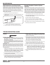
Figure 12. Thermostat Adjustment
NOTE: 1/6 turn of the outer screw equals 12°F (6.7°C).
If recalibration is necessary, with the outer screw at high stop
turn inner adjustment screw clockwise to raise the set point.
NOTE: 1/6 turn of the inner
screw equals 8°F (4.4°C).
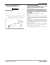
Temperature/Pressure Relief Valve
The temperature/pressure relief valve lever must be operated at
least once a year to ensure that waterways are clear. Certain
naturally occurring mineral deposits may adhere to the valve,
blocking waterways and rendering it inoperative. When the lever
is operated, hot water will discharge from the attached discharge
line if waterways are clear. In addition to annual operation of the
valve lever, the condition of the temperature/pressure relief valve
must be inspected every two to four years by a licensed plumber
or qualified service technician.
Inspect combination temperature/pressure relief valve at
least once every two to four years, depending on local
water conditions. Contact a licensed plumber or qualified
service technician for inspection. Replace valve, if
necessary. DO NOT attempt to self-inspect valve.
BURN HAZARD: Water in unit is very hot. Wear protective
gloves and proper attire when operating to avoid injury.
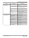
Use the following procedure to test the temperature/pressure
relief valve.
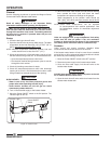
1. Make sure a properly installed
discharge line is connected to
the relief valve. The discharge
line must direct the flow of hot
water from the valve to a
proper place of disposal.
2. Pull up slightly on the relief valve
lever. The lever is connected to
a strong spring, so it will take
some force to move the lever.
• If water flows freely from the
discharge line, the valve is
clear and operating properly.
Release the lever down into the closed position (vertical).
• If water does not flow freely from the discharge line, the
valve is obstructed and must be replaced immediately.
Release the lever, turn off the booster water heater, and
contact a trained, licensed plumber to replace the valve.
NOTE: If dripping or discharge occurs when the relief valve
lever is in the closed position (vertical), turn off the
booster water heater and contact a licensed plumber
immediately. Discharge may indicate that an unsafe
temperature or pressure condition exists.
Temperature/Pressure
Relief Valve Lever
(Closed Position)
Discharge
Line
WARNING
Outer
Adjustment
Screw
Inner
Adjustment
Screw