


IMPORTANT SAFETY INFORMATION
Form No. EBOOSTERBWM-1009
1
ELECTRIC SHOCK HAZARD:
• This unit must be installed by qualified, trained
installers. Installation must conform to all local
electrical and plumbing codes. Check with your local
plumbing and electrical inspectors for proper
procedures and codes.
• Turn power OFF at disconnect switch/circuit breaker
and allow unit to cool before performing any
maintenance or cleaning.
• Consult a licensed electrical contractor for proper
electrical installation conforming to local electrical
codes and the National Electrical Code (N.E.C.).
• Unit is not weatherproof. Locate unit indoors where
ambient air temperature is a minimum of 70°F (21°C).
• Do not place aftermarket covers on or over booster
water heater. Doing so can cause temperature and
moisture build-up resulting in premature failure and
electrical shock.
• This unit must be serviced by qualified personnel only.
Service by unqualified personnel may lead to electric
shock or burn.
• Use only Genuine Bradford White Replacement Parts
when service is required. Failure to use Genuine Bradford
White Replacement Parts will void all warranties and may
subject operators of the equipment to hazardous
electrical voltage, resulting in electrical shock or burn.
Genuine Bradford White Replacement Parts are specified
to operate safely in the environments in which they are
used. Some aftermarket or generic replacement parts do
not have the characteristics that will allow them to operate
safely in Bradford White equipment.
EXPLOSION HAZARD: Do not store or use gasoline or
other flammable vapors or liquids in the vicinity of this or
any other appliance.
Bradford White has always endorsed the use of safety
equipment when using an booster water heater or storage-
type water heater. Bradford White booster water heaters
are shipped with a temperature/pressure relief valve at no
extra charge. This valve must be installed into the marked
opening provided in the tank. Valves supplied with this
booster water heater are designed for high temperature
commercial operation. Do not substitute these valves with
valves designed for domestic water heaters.
Temperature/pressure protective equipment should not be
less than a combination temperature/pressure relief valve
certified by a nationally recognized testing laboratory that
maintains periodic inspection of the production of this
equipment and meets the requirements for Relief Valves
and Automatic Shutoff Devices for Hot Water Supply
Systems, ANSI Z21.22-1979. The temperature/pressure
relief valve must be marked with a minimum set pressure
not to exceed the marked hydrostatic test pressure of the
booster heater as noted on the unit specifications.
Do not connect an expansion tank of any type to booster
water heater lines.
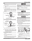
WARNING
FOR INSTALLING COMBINATION TEMPERATURE/
PRESSURE RELIEF VALVES IN ACCORDANCE WITH
AMERICAN NATIONAL STD. Z21.22-1979. Combination
temperature/pressure relief valves with extension
thermostats must be installed so that the temperature-
sensing element is immersed in the water within the top 6"
(152 mm) of the tank. They must be installed either in the
hot outlet service line or directly in a tank tapping.
Combination temperature/pressure relief valves that do
not have extension elements must be mounted directly in
a tank tapping located within the top 6" (152 mm) of the
tank, and shall be adequately insulated and located so as
to assure isolation from the flue gas heat or other ambient
conditions that are not indicative of stored water
temperature. TO AVOID WATER DAMAGE OR SCALDING
DUE TO VALVE OPERATION, DRAIN PIPE MUST BE
CONNECTED TO VALVE OUTLET AND RUN TO A SAFE
PLACE OF DISPOSAL. Discharge line must be as short as
possible and be the same size as the valve discharge
connection throughout its entire length. Drain line must
pitch downward from the valve and must terminate
between 1-1/2" (38 mm) and 6" (152 mm) above the floor
drain where any discharge will be clearly visible. The drain
line shall terminate plain, not threaded, with material
serviceable for temperatures up to 250°F (121°C) or
greater. Excessive length, over 30' (9144 mm), or use of
more than four elbows can cause a restriction and reduce
the discharge capacity of the valve. No shut-off valve shall
be installed between the relief valve and tank, or in the
drain line. Valve lever must be tripped periodically to
assure that waterways are clear. This device is designated
for emergency safety relief and shall not be used as an
operating control. The valves are set to relieve at 150 psi
(1034 kPa) or when water temperature reaches 210°F
(99°C). Read tag on valve for additional information.
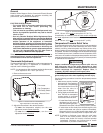
Inspect combination temperature/pressure relief valve at
least once every two to four years, depending on local
water conditions. Contact a licensed plumber or qualified
service technician for inspection. Replace valve, if
necessary. DO NOT attempt to self-inspect valve.
Use only plumbing material suitable for a minimum water
temperature of 200°F (93°C). Materials used must meet
National Sanitation Foundation (NSF) specifications and
all local plumbing codes and regulations.
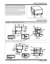
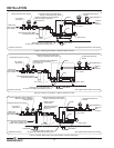
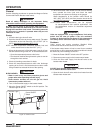
Install booster water heater in horizontal position with
base parallel to the floor and inlet connection at the lowest
point. If installing with legs, mount on floor. If installing
with slide brackets, mount under dish table. DO NOT
mount on walls or in ceiling. Unit must be accessible for
service. Improper installation could create an unsafe
condition.
Valves supplied with this booster water heater are
designed for high temperature commercial operation. Do
not substitute these valves with valves designed for
domestic water heaters.
WARNING
Read the following important safety information before using this equipment to avoid serious injury or death
and to avoid damage to equipment or property.