


EN | 128 Installation and Operating Manual | VIP X2
Appendix Bosch Security Systems | 2006-12 | V2.5
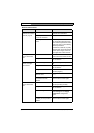
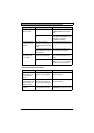
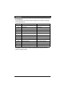
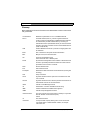
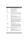
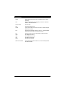
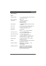
Pin assignment
The pin assignment for the serial interface depends on the interface mode that
is used (see page 84):
To operate the alarm inputs, connect each alarm input to a ground contact
(GND) via a trigger contact.
Contact RS232 function RS422/485 function
IN1 Alarm input 1 Alarm input 1
IN2 Alarm input 2 Alarm input 2
IN3 Alarm input 3 Alarm input 3
IN4 Alarm input 4 Alarm input 4
GND GND (ground) GND (ground)
GND GND (ground) GND (ground)
R (top) Relay Relay
R (bottom) Relay Relay
CTS CTS (clear to send) RxD- (receive data minus)
RTS RTS (ready to send) TxD- (transmit data minus)
RXD RxD (receive data) RxD+ (receive data plus)
TXD TxD (transmit data) TxD+ (transmit data plus)
+ 12 V (power supply) 12 V (power supply)
– GND (ground) GND (ground)