


Bosch | 09/04 | 74-06200-000-F14
D2071A | Operations & Installation Guide |
Set the 12 V Mode to YES. Refer to Section 2.7.1 Battery
for battery installation instructions.
NFPA 72 applications require
110 VAC or 120 VAC,
60 Hz commercial power for the transformer to be
unswitched and from a reliable source. NFPA 72
applications need a dedicated branch circuit to supply
the
110 VAC or 120 VAC transformer power. Identify
the method of disconnecting the circuit as a fire alarm
control circuit. Only authorized personnel can
disconnect the circuit.
Never share the transformer with other
equipment. Foreign grounds on the AC input
damage the D2071A power circuit.
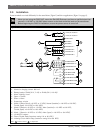
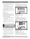
2.6.2 24 VDC Mode
Connect a 24 VDC, uninterrupted, regulated, auxiliary
output from an FACP to Terminals 1 and 2. Set the
12 V Mode to NO. Terminals 1 (+) and 2 (-) are polarity
protected when the D2071A is programmed for the
24 VDC Mode.
Do not connect a 12 VDC standby battery
and do not connect earth ground to the
D2071A when it is in 24 VDC Mode.
The discharge and recharge schedule in Table 4 shows
the voltages at Terminals 1 and 2 used to generate
Battery Reports with the D2071A in 24 VDC Mode. If
the voltage falls below 11.1 VDC, the D2071A does not
operate.
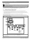
2.7 Secondary Power Supply and
Charging Circuit (12 VAC Mode Only)
Use Terminals 4 and 5 for secondary power
supply and charging circuit connections.
2.7.1 Battery
The D2071A’s charging circuit is only calibrated for
lead-acid type batteries. Do not connect D2071A to a
battery when it is using 24 VDC from an existing
FACP. The battery supplies power to the system during
interruptions in primary power (AC) while in 12 VAC
Mode.
For NFPA 72 applications, use a 12 VDC, 2.3 Ah,
sealed, lead-acid, rechargeable battery (Model D1219).
You can also use a 12 VDC, 7 Ah, sealed, lead-acid,
rechargeable battery (Model D126) that exceeds the
standby requirements.
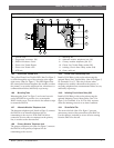
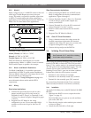
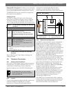
Installation
1. Install the battery in an upright position at the base
of the metal enclosure.
2. Use the black lead to connect the negative side
(black) to the D2071A Terminal 4.
3. Use the red lead to connect the positive side (red) to
the D2071A Terminal 5.
Parallel Activation on Powerup: The Phone Line
Trouble Buzzer, Phone Line Trouble Relay, and Phone
Line Trouble LED briefly activate on AC or battery
powerup to indicate the DACT is operational.
Replacement
Under normal use, replace the battery every 3 to
5 years.
Do not install the transformer in a power
source that is routinely switched off. This
does not comply with NFPA standards and
causes heavy battery discharges that can
result in premature failure.
Supervision
During an AC power loss, the battery supplies all power
to the D2071A and slowly discharges. When the battery
voltage drops below 11.8 VDC, the D2071A sends a
TROUBLE ZN 9 Report to the receiver.
After the AC is restored, the battery begins to charge.
At 13.4 V, the D2071A sends a Battery Restoral Report
(RESTORAL ZN 9).
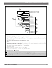
2.0 Installation
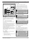
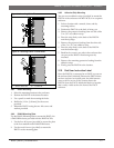
Discharge Cycle
27.6 V FACP battery float voltage
21.8 V Battery Trouble Report
11.1 V (TROUBLE ZN 9) Disable
Recharge Cycle
AC on FACP battery recharging begins
24.7 V Battery Restoral Report (RESTORAL ZN 9)
27.6 V FACP battery charged
Notes:
1. The source supervised is the 24 VDC input from the
FACP.
2. This schedule applies to Terminals 1 and 2 on the
D2071A.
3. The actual voltage can vary ±5%.
Table 4: 24 VDC Battery Discharge and Recharge
Schedule