


Maintenance
3-5 JET ASSEMBLY
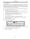
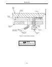
The HS-20 jet assembly consists of several subassemblies. The lower jet assembly consists of the jet
base and stages 3 and 4. A jet shield is provided for the third stage jet. The second stage jet is
secured to the central tube and forms a subassembly. A shield is provided for the second stage jet.
The top of the central tube carries an orifice plug. The top jet spacer passes through this plug and by
a spring-loaded coupling and tie rod secures all stages firmly.
All external and accessible internal surfaces of the jet assembly have been cleaned prior to shipment.
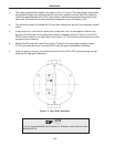
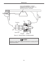
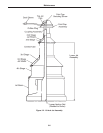
3-5-1 Disassembling the Jet Assembly (Refer to Figure 3-2)
a Disassemble the cold cap water line feedthrough compression seals by removing the nut, the
follower, and the gasket from the side of the pump.
b Remove the cold cap securing screw and withdraw the cold cap assembly carefully. Be sure
that the seal sleeves are not scored or otherwise damaged.
c Firmly grasp the jet cap and unscrew it from the coupling assembly.
d Remove the orifice plug.
e Withdraw the central tube complete with second stage jet and jet shield.
f Raise the lower jet assembly which consists of the third stage jet, the jet shield, the fourth
stage jet, and the jet base.
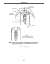
3-5-2 Disassembling the Lower Jet Assembly
a Remove the third stage shield.
3-5
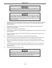
NOTE
________
Before removing the securing screws in the following step, scribe a ref-
erence mark at the interface to assure that original holes are mated
when reassembled.
b Remove the securing screws between the third and fourth stage jets. Carefully preserve the
screws. Be sure that the jet spacers are not damaged in handling.
c Carefully remove the fourth stage jet from the jet base.
d Clean all parts thoroughly.