


7
CF375 Burner Manual
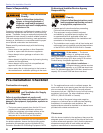
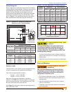
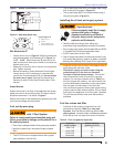
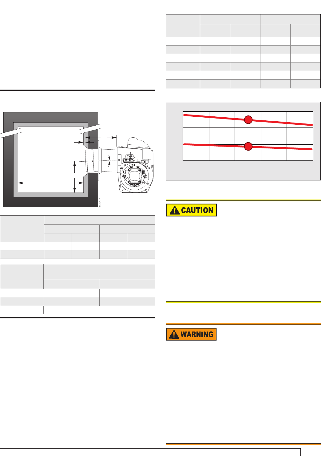
Verify fi ring rate
Refer to appliance manufacturer’s instructions (if available)
for fi ring rate and nozzle selection. Otherwise, the maximum
recommended fi ring rate for the burner depends on the
length of the fi ring chamber and the distance from the
burner center to the chamber fl oor. Verify that the chamber
dimensions are at least as large as the minimum values
given in Figure 3. If the appliance dimensions are smaller
than recommended, reduce the fi ring rate accordingly.
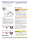
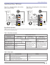
Figure 3 - Dimensions: Minimum Combustion
Chamber and Air Tube Mounting.
Section: Pre-Installation Checklist
Stray Light
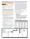
Table 2 - Air Tube Capacities vs. Firebox Pressure
Firebox
pressure
(in w.c.)
No Reserve 10% Turndown
Tube KY Tube KZ Tube KY Tube KZ
0.0” 2.0 3.5 1.8 3.2
0.1” 1.9 3.3 1.7 3.0
0.2” 1.8 3.3 1.6 3.0
0.3” 1.8 3.2 1.6 2.9
0.4” 1.7 3.2 1.5 2.9
0.5” 1.7 3.1 1.5 2.8
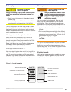
Dust and Moisture
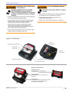
Protect Against Stray Light
Lockout
Failure to follow these instructions could cause
loss of burner operation resulting in no heat, an
unplanned process interruption, work stoppage
and the potential for frozen plumbing or other cold
weather property damage.
The control must detect a dark, no-fl ame condition in
order to start the burner or it will hold in the stray light
lockout mode.
Shield the burner from direct exposure to intense light.
y
y
Protect Against Dust and
Moisture
Wet, dusty environments could lead to blocked
air passages, corrosion damage to components,
impaired combustion performance and result in
asphyxiation, explosion or fi re.
This burner is designed for clean, dry installations.
Electrical controls are not protected against rain or
sprayed water.
Keep the installation clear of dust, dirt, corrosive
vapors, and moisture.
Protective covers and more frequent maintenance
may be required.
y
y
y
y
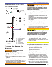
Verify air tube
The information in this section may be disregarded if the
air tube is supplied by the appliance manufacturer.
Two tube arrangements are available:
Tube A — 1.65 to 2.00 GPH
Tube B — 2.00 to 3.75 GPH
Maximum fi ring capacity depends on the fi rebox
pressure. Use Table 2 to verify the correct air tube type
for the fi ring rate required. Use Tube B only when Tube
A cannot provide the fi ring rate required.
See Figure 3 to verify the correct air tube length and air
tube combination code.
* Install burner with
2° pitch as shown.
*2°
L
H
1/4”
T
Firing Rate
Minimum Dimensions
(refractory-lined) (wet-base boilers)
HLHL
1.65 to 2.00 gph 5.5” 12.0” 5.5” 12.0”
2.00 to 3.75 gph 6.0” 15.0” 6.0” 20.0”
Air Tube
Length
(Dimension T)
A.T.C. Codes
(A.T.C. = Air Tube Combination)
Tube A Tube B
05.75” CF56KY CF56KZ
10.00” CF100KY CF100KZ
14.00” CF140KY CF140KZ
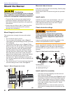
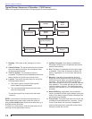
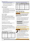
Figure 4 -
Firebox Pressure: CF375 with no Reserve Air
0.1 0.2 0.3 0.4 0.5
0.0
4
3
2
1
Firebox Pressure in Inches W.C.
Maximum Firing Rate U.S. GPH
KZ
KY