17
CF375 Burner Manual
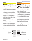
- Priming the Pump For 7505 Control:
Initiate a call for heat.
After the burner starts, press and hold the reset
button for 15 seconds until the yellow light turns on.
This indicates that the button has been held long
enough.
Release the reset button. The yellow light will turn
off and the burner will start up again.
At burner start up, click the reset button while the
igniter is still on. This will transition the control
to a dedicated Pump Prime mode, during which
the motor, igniter, and valve are powered for four
minutes. The yellow light will be on.
Bleed the pump until all froth and bubbles are
purged. If desired, terminate the call for heat or hold
the reset button for at least one second to exit Pump
Prime mode and return to Standby.
At the end of 4 minutes, the yellow light will turn off
and the control will automatically return to standby
mode
.
If prime is not established during the four minute
pump prime mode, start the burner and click the
reset button to re-enter Pump Prime mode. Repeat
the priming procedure until the pump is fully primed
and the oil is free of bubbles.
Terminate the call for heat, and the control will
resume normal operation.
- Priming the Pump For 7184 Control:
Initiate a call for heat
While the ignition is on, press and release the reset
button on the control (hold 1/2 second or less).
If the control has not locked out since it’s most
recent complete heat cycle, the lockout time will be
extended to 4 minutes (45 seconds in earlier units),
and the ignition will remain on the entire heat cycle.
Bleed the pump until all froth and bubbles are
purged. If prime is not established within the
extended lockout time, the control will lock out.
Press the reset button to reset the control and return
to the functions listed in the previous step.
Repeat the previous steps if needed, until the
pump is fully primed and the oil is free of bubbles.
Then terminate the call for heat, and the control will
resume normal operation.
Disable function (7505 or R7184 Controls)
Any time the motor is running, press and hold the reset
button to disable the burner. The burner will remain off
as long as the button is held and will return to standby
when released.
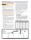
Cad Cell Resistance Measurement
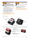
If the Beckett 7505 control is equipped with the
GeniSys Display Module, part 52067U, the cad cell
resistance can be selected and read on the LCD
○
○
○
○
○
○
○
○
○
○
○
○
○
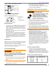
Section: Start the Burner
Oil burning equipment shall
be connected to fl ues having
suitable pressure (draft) at all times to assure
safe and proper operation of the burner.
screen. Also, the GeniSys Contractor Tool, part
52082U, can be used for this purpose.
If these are not available, the cad cell leads can
be unplugged from the control and the resistance
measured with a meter in the conventional way.
Conduct these tests with fl ame present.
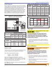
Flame Detection Range
Normal = 0 to 1600 ohms
Limited = 1600 ohms to lockout
Resetting From Restricted or Hard Lockout
If the control continues to lockout without a satisfi ed
call for heat, or fails the motor relay check, the
control enters Hard (restricted) Lockout in order to
limit accumulation of unburned oil in the combustion
chamber
To reset 7505, hold the button down for 15 seconds
until the red light turns off and the yellow light turns
on.
To reset R7184 control hold reset button down for 30
seconds until the LED fl ashes once for one second.
Set combustion using instruments
○
○
○
○
Allow the burner to run for approximately 5 to 10
minutes.
Set the stack or over-fi re draft to the level specifi ed
by the appliance manufacturer.
Natural Draft Applications; typically over-fi re
draft is -0.01” or -0.02” w.c.
Direct Venting; typically may not require draft
adjustment.
High Effi ciency/Positive Pressure Appliances;
also vary from traditional appliances (see
manufacturer’s recommendations).
Follow these four steps to properly adjust the
burner:
Step 1: Adjust the air shutter/band until a trace of
smoke is achieved.
Step 2: At the trace of smoke level, measure the
CO
2
(or O
2
) . This is the vital reference point for
further adjustments. Example: 13.5% CO
2
(2.6%
O
2
)
Step 3: Increase the air to reduce the CO
2
by
1.5 to 2 percentage points. (O
2
will be increased
by approximately 2.0 to 2.7 percentage points.)
Example: Reduce CO
2
from 13.5% to 11.5% (2.6%
to 5.3% O
2
).
1.
2.
○
○
○
3.


