


16
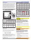
Table 5 - Initial indicator adjustment plate
settings (head position)
Approximate adjusting
plate setting
Firing rate, gph
0 1.65
1 1.75
3 2.00
4 2.50
5 3.00
6 3.50
Note: These settings are approximate, and can vary depending on
actual job conditions and overfi re pressure.
Section: Start the Burner
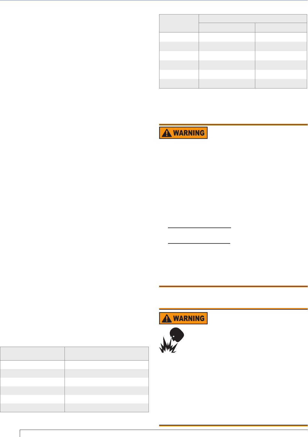
Table 6 - Initial air shutter and band settings
Firing rate,
gph
Approximate air settings
Shutter Band
1.65 5 0
1.75 10 2
2.00 10 4
2.50 10 5
3.00 10 6
3.50 10 8
Note: These settings are approximate, and can vary depending on
actual job conditions and overfi re pressure.
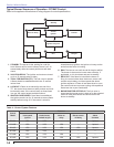
Appliance has been fi lled with water (boilers) and
controls have been operationally checked.
Burner has been installed in accordance with appliance
manufacturer’s instructions (when available).
Also refer to appliance manufacturer’s instructions
(when available) for start-up procedures.
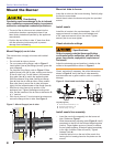
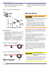
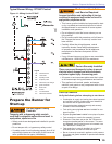
Initial head position
(Reference Figure 8)
The indicator plate assembly markings correspond
to head position settings.
Loosen the fastener (Figure 8, item d) and slide the
indicator plate until the number on the indicator plate
corresponds to the initial head setting listed in Table
5, for the desired fi ring rate.
When the head position has been set, tighten the
fastener and the spline nut.
Initial air settings
(Reference Table 6)
Loosen the air band and shutter, and adjust to the
approximate fi ring rate settings given in Table 6.
These initial settings should be adequate for starting the
burner. Once the burner is in operation, the air settings
will be adjusted for best performance as discussed later
in this manual.
Follow the procedures described later in this manual for
fi ne-tuning the air settings.
Set appliance limit controls
Set the appliance limit controls in accordance with the
appliance manufacturer’s recommendations.
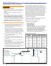
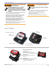
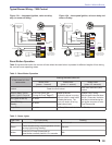
Prepare the fuel unit for air venting
To vent air from one-pipe oil systems, attach a clear
hose to the pump air bleed valve (fi gure 10 & 11) on the
fuel unit. Provide a container to catch the oil. Loosen the
pump air bleed valve.
Vent the air as described in the next section under Start
the burner.
□
□
□
○
○
○
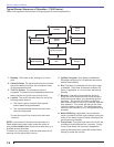
Start the Burner
Explosion and Fire Hazard
Failure to follow these instructions could lead to
equipment malfunction and result in heavy smoke
emission, soot-up, hot gas puff-back, fi re and
asphyxiation hazards.
Do not attempt to start the burner when excess oil has
accumulated in the appliance, the appliance is full of
vapor, or when the combustion chamber is very hot.
Do not attempt to re-establish fl ame with the burner
running if the fl ame becomes extinguished during
start-up, venting, or adjustment.
Vapor-Filled Appliance: Allow the unit to cool off and
all vapors to dissipate before attempting another start.
Oil-Flooded Appliance: Shut off the electrical power
and the oil supply to the burner and then clear all
accumulated oil before continuing.
If the condition still appears unsafe, contact the Fire
Department. Carefully follow their directions.
Keep a fi re extinguisher nearby and ready for use.
y
y
y
y
y
y
Hot Gas Puff-back and
Heavy Smoke Hazard
Failure to bleed the pump properly could
result in unstable combustion, hot gas
puff-back and heavy smoke.
Do not allow oil to intermittently spray into a hot
combustion chamber while bleeding.
Install a gauge in the nozzle discharge port tubing or
fully open the pump bleed valve to prevent oil spray
from accumulating in the combustion chamber when
venting air from the fuel pump.
Ensure that all bubbles and froth are purged from
the oil supply system before tightening the pump air
bleed valve.
y
y
y
Starting the burner and venting air