


10
Burner fuel fl ow
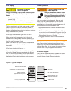
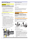
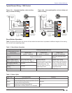
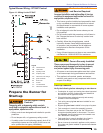
One-pipe systems – See Figure 10 for the fuel fl ow path.
Oil supply connects to one of the fuel unit inlet ports.
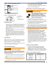
Two-pipe systems – See Figure 11 for the fuel fl ow paths
for two-pipe oil systems.
Oil supply connects to one of the fuel unit inlet ports. Oil
return connects to the fuel unit return port. (Install the by-
pass plug in the fuel unit for two-pipe systems.)
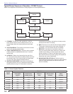
Nozzle pressure – The fuel unit nozzle port pressure
is factory set at 140 psig. Some original equipment
○
○
○
○
○
manufacturer burner applications may call for a lower
pressure to obtain a required fi ring rate. Do not change
this pressure unless directed to do so by the appliance
manufacturer.
125-200 psig
125-200 psig
3503
125-200 psig
125-200 psig
3502
Figure 10 - One-pipe oil fl ow (A pump)
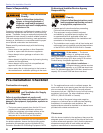
Wire the Burner
Electrical Shock Hazard
Electrical shock can cause severe personal injury or death.
Disconnect electrical power before installing or
servicing the burner.
Provide ground wiring to the burner, metal control
enclosures and accessories. (This may also be
required to aid proper control system operation)
Perform all wiring in compliance with the National
Electric Code ANSI/NFPA 70 (Canada CSA C22.1).
y
y
y
Legend
a Return port
b Nozzle port
c Oil valve
d Nozzle & adapter
g Inlet port
k Return line to oil tank
p Air bleed valve
Figure 11 - Two-pipe oil fl ow (A or B pumps)
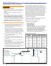
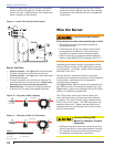
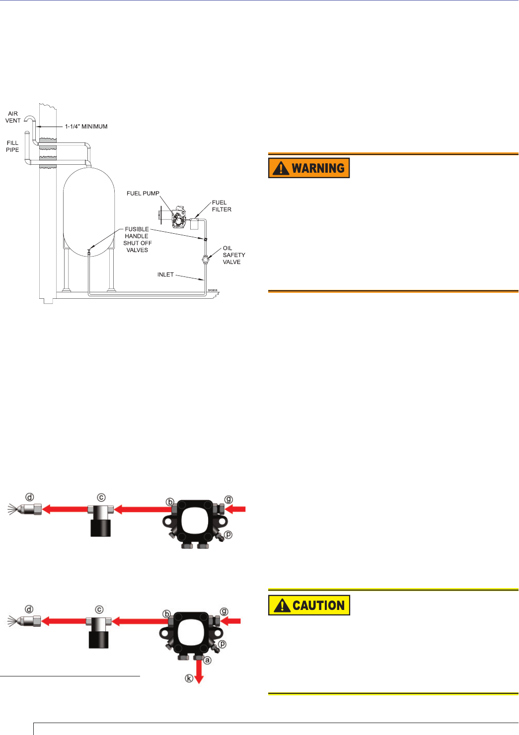
Figure 9 – Inside Tank Gravity Feed System
Install two high-quality shut-off valves in accessible
locations on the oil supply line. Locate one valve
close to the tank. Locate the other valve close to the
burner, upstream of the fuel fi lter.
○
Section: Wire the Burner
Incorrect Wiring Will
Result in Improper Control
Operation
GeniSys wiring label colors may not match the wire
colors of the burner or other manufacturers’ controls.
The GeniSys Control should be wired according to
the appliance manufacturer’s instructions.
y
y
Install the burner and all wiring in accordance with the
National Electrical Code and all applicable local codes
or requirements. In Canada, comply with the Canadian
Electrical Code, Part 1.
Wire the burner in compliance with all instructions
provided by the appliance manufacturer. Verify operation
of all controls in accordance with the appliance
manufacturer’s guidelines.
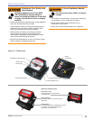
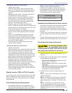
See Figure 13a or 13b for a typical wiring diagram with
the 7505 oil primary, for reference purposes only. See
Figure 14 for a typical wiring diagram with the R7184 oil
primary, for reference purposes only.
The 7505 primary control with valve-on delay (pre-
time) and burner motor-off delay (post time) requires
a constant 120 volts AC power source supplied to the
BLACK wire on the control. The RED wire goes to the
appliance limit circuit. Please note that other control
manufacturers may use different wire colors for power
and limit connections.
OIL
TANK