


7
Form 6104 BCF23-R05
Verify air tube
The information in this section may be disregarded if the
air tube is supplied by the appliance manufacturer.
On the CF1400, there are two tube arrangements
available –
Tube A — 4.0 to 11.0 GPH per Table 2
Tube B — 7.0 to 13.6 GPH per Table 2
The CF1400 maximum fi ring capacity depends on
the fi rebox pressure. Use Table 2 to verify the cor-
y
y
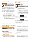
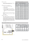
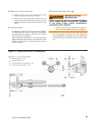
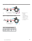
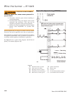
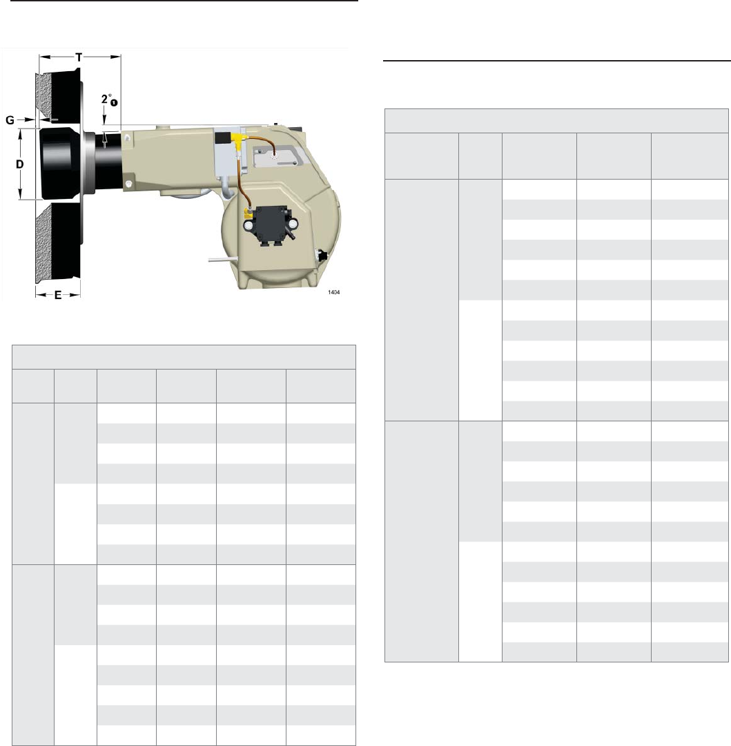
Figure 3 – Air tube mounting dimensions
Note: Install the burner with a 2° pitch as shown.
Note: 10% turndown indicates suffi cient reserve air to reduce
the CO
2
in the fl ue to 90% of its value.
Note: The above ratings may vary 5% due to variations in
actual job conditions.
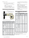
Table 2 - Air tube capacity Versus fi rebox
pressure
rect air tube type for the fi ring rate required. Use
Tube B only when Tube A cannot provide the fi ring
rate required.
On the CF2300, there are two tube arrangements
available –
Tube A — 7.0 to 19.9 GPH per Table 2
Tube B — 10.0 to 19.9 GPH per Table 2
The CF2300 maximum fi ring capacity depends on
the fi rebox pressure. Use Table 2 to verify the cor-
rect air tube type for the fi ring rate required. Use
Tube B only when Tube A cannot provide the fi ring
rate required.
See Figure 3 to verify the correct air tube length and
air tube combination code.
y
y
y
Air Tube Combination Codes
Model Tube
Dimention
T
Dimention
D
Code
Dimension
E
CF1400
A
6.75” 5.5” CF 66 KD -
10.25” 5.5” CF 102 KD -
13.75” 5.5” CF 136 KD -
17.75” 5.5” CF 176 KD -
B
6.75” 5.75” CF 66 KE -
10.25” 5.75” CF 102 KE -
13.75” 5.75” CF 136 KE -
17.75” 5.75” CF 176 KE -
CF2300
A
6.75” 6.5” CF 66 KG 2.94”
10.25” 6.5” CF 102 KG 2.94”
13.75” 6.5” CF 136 KG 2.94”
17.75” 6.5” CF 176 KG 2.94”
B
6.75” 8.125” CF 66 KS 3.69”
8.375” 8.125” CF 86 KS 3.69”
11.0” 8.125” CF 110 KS 3.69”
14.5” 8.125” CF 144 KS 3.69”
18.5” 8.125” CF 184 KS 3.69”
Air Tube Capacity vs Firebox Pressure
Model Tube
Firebox
Pressure
(In W.C.)
No Reserve
Air
10% Turndown
(GPH)
CF1400
A
0.0 - 11.0
0.2 - 10.5
0.4 - 10.1
0.6 - 9.6
0.8 - 9.2
1.0 - 8.7
B
0.0 13.6 12.2
0.2 13.1 11.7
0.4 12.5 11.2
0.6 12.0 10.8
0.8 11.4 10.3
1.0 10.9 9.8
CF2300
A
0.0 19.9 19.9
0.2 19.2 19.1
0.4 18.5 18.3
0.6 17.9 17.6
0.8 17.2 16.8
1.0 16.5 16.0
B
0.0 19.9 19.9
0.2 19.7 19.6
0.4 19.5 19.3
0.6 19.4 19.1
0.8 19.2 18.8
1.0 19.0 18.5
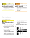
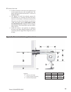
Legend
E
Insertion depth
G
Air tube to inside of chamber: .25” ±.125”
T
Nozzle centerline to electrode tip - 1/4”
D
Nozzle face to electrode tip - 1/8”