


5
Form 6104 BCF23-R05
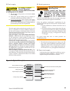
Nozzle pressure
The fuel unit nozzle port pressure is factory set at 300
psig. Some original equipment manufacturer burner
applications may call for a lower pressure to obtain a
required fi ring rate. Do not change this pressure un-
less directed to do so by the appliance manufacturer.
Electrical supply
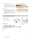
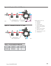
Verify that the power connections available are correct
for the burner. Refer to Figure 1. All power must be
supplied through fused disconnect switches.
y
Fuel supply
The fuel supply piping and tank must provide #1 or #2
fuel oil at pressure or vacuum conditions suitable for
the fuel unit (oil pump) on the burner. Refer to fuel unit
literature in the literature envelope in the burner carton to
verify allowable suction pressure.
When fuel supply is level with or higher than burner
fuel unit —When the fuel unit is not required to lift the
oil, the installation is usually suitable for either a one-
pipe or two-pipe oil system. The oil pressure at the inlet
of the fuel unit must not exceed 3 psig.
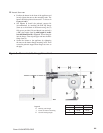
The fuel unit is shipped with the by-pass plug installed.
Leave the by-pass plug installed for all low/high fi ring
burners, regardless whether one-pipe (with by-pass
loop) or two-pipe. See Figure 9 for installation of the by-
pass loop required for one-pipe fuel supply installations.
See Figure 10 for connections to the fuel unit for two-
pipe fuel supply installations.
When fuel supply is below the burner fuel unit —Use
a two-pipe oil system when the fuel unit must lift the oil
more than 8 feet. The return line provided by the two-pipe
system is needed to minimize the effects of air-related
problems during operation.
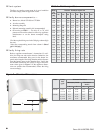
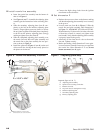
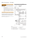
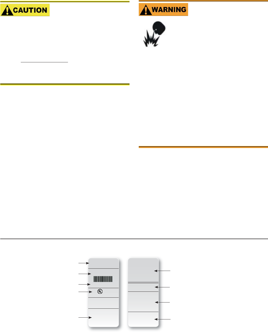
LISTED
(FUEL) BURNER
SERIAL NUMBER
050214-00000
Control Circ: 120V/60Hz 4.5A
Motor Circ: 120V/60Hz 4.0A
Model “XX”
Series (Fuel) Burner
R.W. Beckett Corp.
Elyria, Ohio
Made in the U.S.A.
For use with Group 8 . . .
MP 1192 XX000 R00
X
X
X
X
X
X
XX000 R00
050214-00000
MFR’S SETTINGS
R.W. Beckett Construction & Setting Data
R.W. Beckett Specifi cation
Number and Revision
Boiler Manufacturer and
Model, When Applicable
Additional Codes
General Model Information
Serial Number,Including Date Code
Rating Information
Approval Agency Symbols
Primary Group and Fuel
L0002
Figure 1 – Typical Nameplate
The oil supply inlet pressure to the burner cannot
exceed 3 psig.
Insure that a pressure limiting device is installed in
accordance with the latest edition of NFPA 31.
Gravity Feed Systems: Always install an anit-siphon
valve in the oil supply line or a solenoid valve (RWB
Part # 21789) in the pump/nozzle discharge tubing to
provide backup oil fl ow cut-off protection.
y
y
y
Damage to the fi lter or pump seals could cause
oil leakage and a fi re hazard.
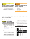
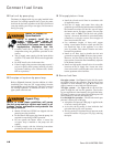
Oil Supply Pressure
Control Required
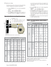
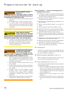
Use only nozzles having the brand, fl ow rate (gph), spray angle
and pattern specifi ed by the appliance manufacturer.
Follow the appliance manufacturer’s specifi cations for the
required pump outlet pressure for the nozzle, since this affects
the fl ow rate.
Nozzle manufacturers calibrate nozzle fl ow rates at
100 psig.
This burner utilizes pressures higher than 100 psig,
so the actual nozzle fl ow rate will be greater than the
gph stamped on the nozzle body. (Example: A 8.00
gph nozzle at 150 psig = 9.80 gph and at 300 psig
= 13.86 gph)
For typical nozzle fl ow rates at various pressures see
accompanying chart.
y
y
Incorrect nozzles and fl ow rates
could result in impaired combustion,
under-fi ring, over-fi ring, sooting,
puff-back of hot gases, smoke
and potential fi re or asphyxiation
hazards.
Correct Nozzle and Flow
Rate Required