


10
Form 6104 BCF23-R05
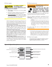
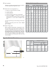
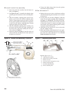
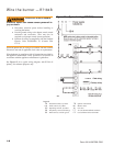
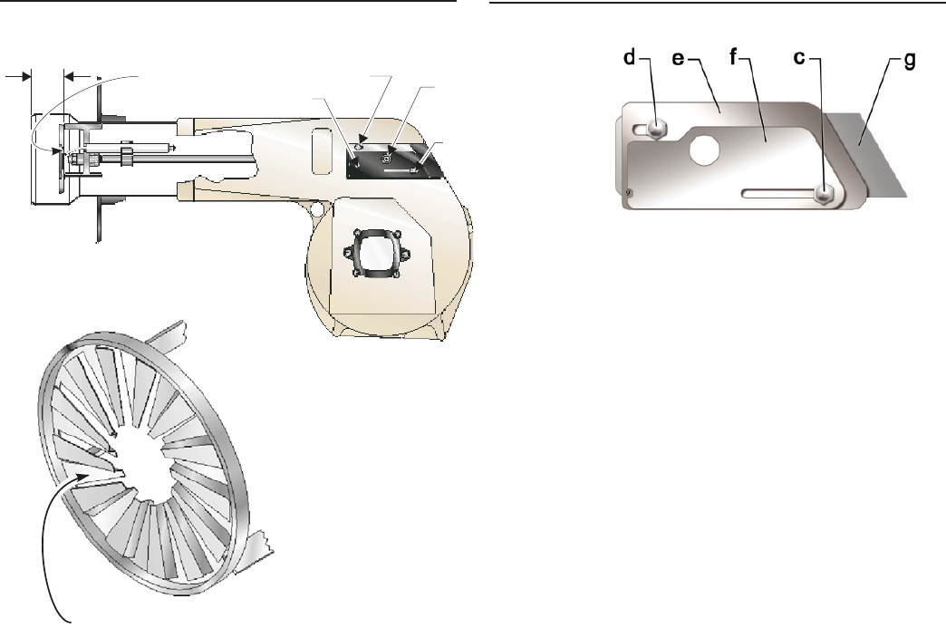
Figure 6 – Nozzle line assembly in burner
Z
2308
a
Measure dimension from
front (flat) face of head to
end of air tube, as shown.
Z
b
c
d
Measure dimension Z from the flat
surface between (not on) the raised fins.
2324
Set dimension Z
Replace the rear access door on the burner, making
sure that the adjusting plate assembly is now securely
in the groove.
Loosen acorn nut (item d) in Figure 5. Slide the
nozzle line and plate assembly until dimension Z
in Figure 5 is 1-3/4 ±1/16” (CF1400 and CF2300).
When dimension Z (from end of air tube to fl at area
of front face of head) is correctly set, tighten acorn
nut (item d). Verify that the adjusting plate assembly
is properly seated in the groove.
Attach the oil line from the oil valve to the nozzle
line end. Tighten securely.
Before proceeding, check dimension Z once again.
Loosen acorn nut (item d) if necessary to reposition
the nozzle line. Once dimension Z is set, do not
loosen acorn nut (item d) again.
y
y
y
y
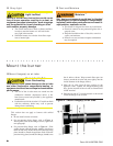
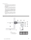
Install nozzle line assembly
Insert the nozzle line assembly into the burner air
tube as in Figure 6.
See Figures 6 and 7. Assemble the adjusting plate
assembly per the instructions in the assembly pack-
et.
Slide the secondary adjusting plate (item f) com-
pletely to the left on the indicator adjusting plate
(item e). Finger-tighten acorn nut (item c) to secure
the two plates together. Slide both plates completely
to the left on the primary adjusting plate (item g)
and fi nger-tighten acorn nut (item d).
Slide the completed adjusting plate assembly over
the nozzle line end. Move the plate assembly and
the nozzle line so the plate assembly fi ts into posi-
tion as shown in Figure 6.
Install the spline nut (Figure 6, item b) on the end
of the nozzle line, leaving the nut loosely placed so
the plates can be moved.
y
y
y
y
y
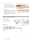
Z = 1-3/4” ± 1/16”
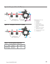
Figure 7 – Adjusting plate assy.
Connect the high-voltage leads from the ignition
transformer to the electrodes.
y
Legend (fi gure 6 & 7)
a
Adjusting plate assembly
b
Spline nut for securing nozzle line
c
Bottom acorn nut
d
Top acorn nut (for setting dim. Z only)
e
Indicator adjusting plate
f
Secondary adjusting plate
g
Primary adjusting plate