


12
Form 6104 BCF23-R05
Models CF1400 and CF2300 are shipped with the
pump bypass plug installed.
Do not remove the bypass plug from the pump. It is
required for step-fi ring (Lo/Hi) operation.
Do not operate the burner unless a return line
or bypass loop is installed or the pump seal will
rupture.
Carefully comply with the following instructions
provided in this section of the manual.
y
y
y
y
Failure to follow these guidelines will cause
the fuel pump seals to rupture and result in oil
leakage, burner malfunction and potential fi re
and injury hazards.
Factory-Installed Pump
Bypass Plug
Connect fuel lines
Fuel unit by-pass plug
The burner is shipped with a by-pass plug installed in the
fuel unit. For low/high operation, the by-pass plug must
be left in the fuel unit, regardless of the fuel system used
(one-pipe with by-pass loop or two-pipe). Do not remove
the by-pass plug.
Oil supply/return lines
Install the oil tank and oil lines in accordance with
all applicable codes.
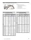
Size the oil supply and return lines using the
guidelines given in the fuel unit literature included in
the literature envelope. Oil line fl ow rate will equal
the burner rate for one-pipe systems. For two-pipe
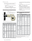
systems, refer to Table 3 for the fuel unit gearset
capacity - the rate at which fuel is recirculated when
connected to a two-pipe system. Size two-pipe oil
lines based on this fl ow rate.
Use continuous lengths of heavy-wall copper
tubing, routed under the fl oor where possible. Do
not attach fuel lines to the appliance or to fl oor
joists if possible. This reduces vibration and noise
transmission problems.
Install an oil fi lter sized to handle the fuel unit
gearset fl ow capacity (Table 3) for two-pipe systems.
However, size the fi lter for the fi ring rate for one-
pipe systems. Locate the fi lter immediately adjacent
to the burner fuel unit.
Install two high-quality shutoff valves in accessible
locations on the oil supply line. Locate one valve
close to the tank. Locate the other valve close to the
burner, upstream of the fuel fi lter.
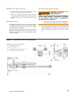
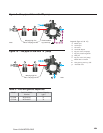
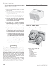
Burner fuel fl ow
One-pipe systems – See Figure 9 for the fuel fl ow paths
for high-fi re and low-fi re operation. The low-fi re by-pass
regulation is done internally for type B fuel units. Oil
supply connects to one of the fuel unit Inlet ports.
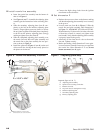
Two-pipe systems – See Figure 10 for the fuel fl ow
paths for high-fi re and low-fi re operation. The low-fi re
by-pass regulation is done internally for type B fuel units.
Oil supply connects to one of the fuel unit Inlet ports. Oil
return connects to the fuel unit Return port.
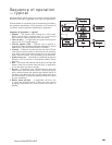
Low-fi re/high-fi re operation – The fuel unit nozzle port
pressure is factory set at 300 psig.
At high fi re, full pressure (300 psig) is applied at the
oil nozzle, causing full input.
At low fi re, the by-passing is done inside the fuel
unit when the by-pass valve operates.
This by-passing of oil reduces the oil pressure at the
nozzle (to between 125 psig and 175 psig), reducing
the input.
y
y
y
y
y
y
y
y
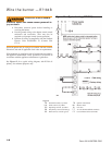
One-pipe oil system by-pass loop
Refer to Figure 9 (item m). Note the addition of a fi eld-
installed by-pass loop (use 3/8” copper tubing) from the
fuel unit Return port to the Inlet port. This line is required
for low/high operation. It simulates the fl ow of a two-
pipe system at the fuel unit.
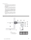
Install Oil Supply To
Specifi cations
Carefully install the oil supply lines, fi ttings and
components using the guidelines provided in this
section.
The oil supply must comply with the latest edition
of NFPA 31 (Canada CSA B139) and all applicable
codes.
Do NOT install valves in the return line.
If the oil supply inlet pressure to the pump exceeds 3
psig or for gravity feed systems, install an oil safety
or pressure reducing valve (Webster OSV, Suntec
PRV or equivalent).
y
y
y
y
Failure to properly install the oil
supply system could cause oil
leakage, equipment malfunction,
puff-back of hot gases, heavy smoke,
asphyxiation, explosion and fi re