


8
Section: Burner Wiring
Explosion, Fire, Scald, &
Burn Hazard
All heating equipment must have HIGH
LIMIT controls to protect against excessive
temperature and/or pressure. The control
must interrupt electrical power and shutdown the
burner, if operating or safety controls fail and cause a
runaway condition.
Follow the equipment manufacturer’s wiring diagrams
and note all required safety controls.
Typical safety controls include high temperature or
pressure limits, low water cutoffs, pressure relief
valves and blocked fl ue sensing switches.
Verify all limit and safety controls are installed and
functioning correctly, as specifi ed by the manufacturer,
applicable safety standards, codes and all authorities
having jurisdiction.
Ensure the equipment is free of oil and oil vapor
before starting or resetting the burner.
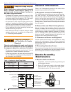
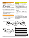
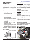
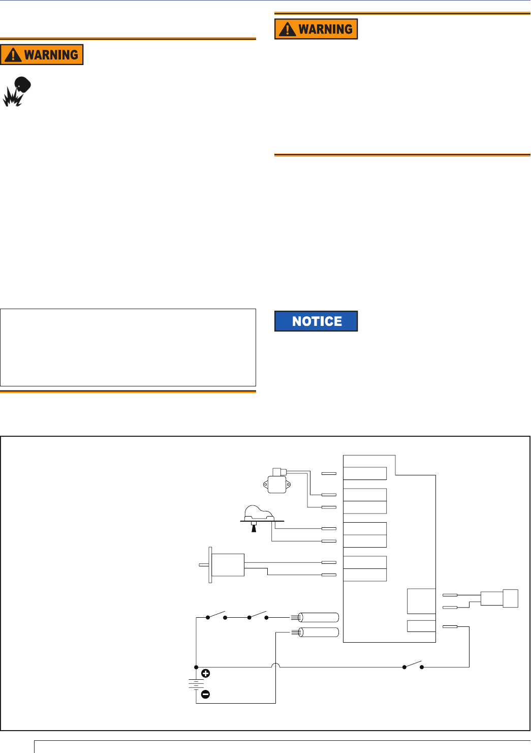
Do not wire power directly to the burner motor. Only
wire the motor as shown in Figure 6. If instant burner
heat is required by the application, purchase or
program a control with a long motor-off delay time,
which will ensure instant heat if a new call for heat
is received within the motor-off delay time.
y
y
y
y
y
Figure 6. Wiring with 7559 Control
Notes:
Wires are to be sized to prevent a
voltage drop between the battery and
the burner with the burner running at
full load.
Fuse Sizes(inside control):
Motor = 20 Amp; Igniter, Control,
Valve, & Alarm = 7.5 Amp
Hard-wire burner ground to battery.
Do NOT use chassis ground system.
Input power to the control’s +24 volt
wire shall be provided from a fused
service switch, rated at 50 amps or
less.
Motor-off delay on a 7559P will be
disabled if the safety and operating
limits as shown in Figure 6 interrupt
power to the control’s red +24 volt
wire.
Do not wire power directly to the
burner motor. Only wire the motor as
shown in Figure 6. If instant burner
heat is required by the application,
purchase or program a control with a
long motor-off delay time, which will
ensure instant heat if a new call for
heat is received within the motor-off
delay time.
1.
2.
3.
4.
5.
6.
24V
POWER
MAIN
ALARM
VALVE
GND (VLV)
IGNITER
GND (IGN)
MOTOR
GND (MTR)
ENABLE
CAD
CELL
ON/OFF/RESET
HIGH
LIMIT
MOTOR
IGNITER
THERMOSTAT
CAD CELL
RED WIRE
BLACK WIRE
OIL
VALVE
Electrical Shock Hazard
Electrical shock can cause severe personal injury or
death.
Remove all jewelry, such as rings and watches before
performing service.
Disconnect electrical power before installing or
servicing the burner.
Provide ground wiring to the burner, metal control
enclosures and accessories. (This may also be
required to aid proper control system operation.)
y
y
y
A. Burner installed on equipment
Refer to appliance manufacturer’s wiring diagram for
electrical connections. Refer to “Maintain & Service
Burner” section near the end of this manual.
B. Burner Replacement
Burner wiring may vary, depending on the actual primary
control and furnished options. Refer to Figure 6 for typical
burner wiring.
Burner Wiring
Variations to the burner circuits may
occur due to optional temperature,
pressure, and vacuum switches that control burner
operation. Note that when external switches are used to
control motor operation they must be sized correctly for
the rated current or a relay should be installed to isolate
the switches from the motor’s full load current.