


12
Troubleshooting
Oil burners that are designed for use on road maintenance
equipment are built to take temperature extremes,
vibration, and rough handling. When performing the
following troubleshooting steps, we assume that the oil
burner motor and ignition transformer operate continuously
and the oil solenoid valve, which controls oil fl ow, is cycled
by the equipment controls. We also assume that there is
power to the burner and fuel in the tank.
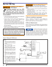
In addition to typical mechanics tools, it is recommended
to have the following equipment on hand.
Meter capable of measuring volts, ohms and amps,
ignition transformer tester,
smoke pump tester,
combustion analyzer, and
0 to 200 psi pressure gauge.
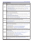
See Table 3 on following page for troubleshooting steps.
○
○
○
○
○
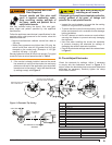
Clean the blower wheel, air inlet, air guide, retention
head and static plate of any dirt, asphalt or other
material.
Check motor current. The amp draw should not
exceed the nameplate rating. Check all wiring for
loose connections or damaged insulation.
Check the pump pressure and cutoff function.
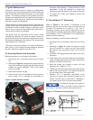
Check primary control safety lockout timing if
applicable. Refer to the information supplied by the
control manufacturer for procedures.
Check ignition system for proper operation.
Inspect the exhaust system for soot accumulation or
other restriction.
Clean the equipment thoroughly according to the
manufacturer’s recommendations.
Check the burner performance using test instruments.
It is good practice to make a record of the service
performed and the combustion test results.
□
□
□
□
□
□
□
□
□
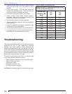
Table 2. Nozzle Flow Rate by Size
Nozzle fl ow rate U. S. gallons per hour of No. 2 fuel
oil when pump pressure (psig) is:
Nozzle size
(rated at 100
psig)
100
psi
140
psi
1.75 1.75 2.07
2.00 2.00 2.37
2.25 2.25 2.66
2.50 2.50 2.96
2.75 2.75 3.24
3.00 3.00 3.55
3.50 3.50 4.13
4.00 4.00 4.70
4.50 4.50 5.30
5.00 5.00 -
Section: Troubleshooting