


10
Explosion and Fire Hazard
Failure to follow these instructions could
lead to equipment malfunction and result
in heavy smoke emission, soot-up, hot gas
puff-back, fi re and asphyxiation hazards.
Do not attempt to start the burner when excess oil has
accumulated in the appliance, the appliance is full of
vapor, or when the combustion chamber is very hot.
Do not attempt to re-establish fl ame with the burner
running if the fl ame becomes extinguished during
start-up, venting, or adjustment.
Vapor-Filled Appliance: Allow the unit to cool off
and all vapors to dissipate before attempting another
start.
Oil-Flooded Appliance: Shut off the electrical power
and the oil supply to the burner and then clear all
accumulated oil before continuing.
If the condition still appears unsafe, contact the Fire
Department. Carefully follow their directions.
Keep a fi re extinguisher nearby and ready for use.
y
y
y
y
y
y
Section: Start Up Burner & Set Combustion
Professional Service
Required
Incorrect installation, adjustment, and
use of this burner could result in severe
personal injury, death, or substantial
property damage from fi re, carbon
monoxide poisoning, soot or explosion.
Please read and understand the manual supplied with this
equipment. This equipment must be installed, adjusted
and put into operation only by a qualifi ed individual or
service agency that is:
Licensed or certifi ed to install and provide technical
service to oil heating systems.
Experienced with all applicable codes, standards and
ordinances.
Responsible for the correct installation and commission
of this equipment.
Skilled in the adjustment of oil burners using
combustion test instruments.
The installation must strictly comply with all applicable
codes, authorities having jurisdiction and the latest revision
of the National Fire Protection Association Standard for the
installation of Oil-burning Equipment, NFPA 31 (or CSA-
B139 and CSA-B140 in Canada). Regulation by these
authorities take precedence over the general instructions
provided in this installation manual.
y
y
y
y
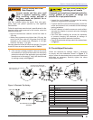
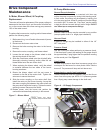
C. Solenoid Valve Testing
To check solenoid operation, perform the following.
Check for oil fl ow and operating pressure by
removing the copper tubing from the nozzle line
and installing a pressure gauge in the line. With
the motor running and the coil energized, check the
gauge. The pressure should read 100 psig unless
otherwise stated.
To check the solenoid valve cutoff function, deadhead
the pressure gauge onto the copper connector tube
attached to the nozzle port. Run the burner for a
short period of time. Shut the burner off. The solenoid
valve should close and the pressure should drop and
hold.
Replace the solenoid valve if it does not pass the
previous steps.
Start Up Burner & Set
Combustion
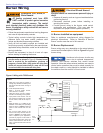
A. Basic Burner Operation
With 7559 Primary Safety Control
The 7559 control provides the benefi ts of added safety,
convenience, and performance. It adds a valve on delay
and motor-off delay to the burner’s operation sequence that
promote clean burner operation. It has a lock-out function
that shuts the burner down if it is not operating properly. The
control adds fusing at the burner to protect against component
failures. The control also has redundant motor relays that are
checked for proper operation every heat cycle.
Variations to the burner circuits may occur due to optional
temperature, pressure, and vacuum switches that control
burner operation. Note that when external switches
are used to control motor operation they must be sized
correctly for the rated current or a relay should be installed
to isolate the switches from the motor’s full load current.
B. Combustion Set-up
As soon as burner motor starts rotating bleed all the air
from the pump. (Required with single-pipe systems.)
To bleed the pump, attach a clear plastic hose over the
vent fi tting. Loosen the fi tting and catch the oil in an empty
container. Tighten the fi tting when all air has been purged
from the supply system. Note: If the burner stops after a
fl ame is established, the unit probably requires additional
bleeding. Continue to bleed the system until the pump is
primed and a fl ame is established when the bleed valve
is closed.
1.
2.
3.
C. Set Combustion with Instruments