


6
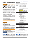
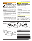
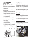
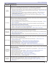
Figure 5. ‘Z’ Dimensions Using Gauge
SK9787
Section: Nozzle Assembly Maintenance
The Beckett Z gauge (part number Z-
2000) is available to permit checking
the F head “Z” dimension without removing the burner.
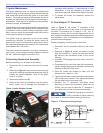
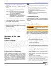
C. Igniter Maintenance
The igniter assembly does not require any adjustments
beyond making sure the springs and the burner electrode
rods make solid contact when the igniter is in the closed
position. The sealing surfaces of the gaskets should be
checked and replaced at the fi rst signs of any damage or
deterioration. Clean any dirt or residue from the porcelain
bushings, springs, and baseplate.
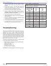
The simplest way to check igniter operation is by supplying
voltage to the input and checking to see whether an arc
is produced. Check by either looking or listening to see if
there is an arc across the electrodes while the burner is
running and the igniter is energized.
The igniter must be grounded to the burner before
checking the following. To check the igniter, ensure all
power to the burner is off and use an ohmmeter to check
the resistance between the two springs. The meter should
read between 480 - 580 ohms.
The igniter should be replaced if the meter indicates an
open circuit, or the spring-to-spring resistance exceeds
the 480 - 480 ohms range by more than 10%.
D. Servicing Nozzle Line Assembly
Before proceeding, turn off power to the burner.
Disconnect the oil connector tube from the nozzle
line.
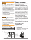
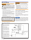
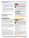
Referring to Figure 4, loosen the two screws securing
the igniter retaining clips (a) and rotate both clips to
release the igniter baseplate. Then tilt the igniter
back on its hinge.
Remove the splined nut (b).
Remove the nozzle line assembly from the burner,
being careful not to damage the electrodes or
1.
2.
3.
4.
insulators while handling. To ease removal of short
assemblies, it may be necessary to loosen the
escutcheon plate (c). Reset to the edge of the label.
To replace the nozzle line assembly, reverse the
above steps.
E. Check/Adjust “Z” Dimension
Refer to Figure 5. The critical “Z” dimension is the
distance from the face of the nozzle to the fl at face of
the head. This distance for F heads is 1-1/8”. The “Z”
dimension is factory set for burners shipped with the air
tube installed but should always be verifi ed during service
and installation. If the “Z” dimension is out of adjustment,
perform the following steps.
Before proceeding, turn off power to the burner.
Disconnect the oil connector tube from the nozzle
line.
Referring to Figure 4, loosen the splined nut (a)
from the nozzle line. Loosen the hex head screw
(b) securing the escutcheon plate to the burner
housing.
A Beckett T650 gauge should be used to set the Z
dimension.
Place the end of a ruler at the face of the nozzle and,
using a straight edge across the head, measure the
distance to the face of the head.
Slide the nozzle line forward or back until this
dimension for F heads is 1-1/8”.
Tighten the hex head screw to secure the escutcheon
plate to the burner chassis. Then tighten the splined
nut and attach the oil connector tube.
Recheck the “Z” dimension periodically when
servicing to ensure the escutcheon plate has not
shifted. You will need to reset the “Z” dimension if
you replace the air tube or nozzle line assembly.
5.
1.
2.
3.
4.
5.
6.
7.
Figure 4. Igniter Retainer Screws
a
b