


SECTION 4
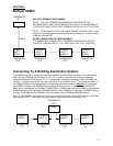
Basic HGM300/RDM800 Monitor System Connection
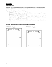
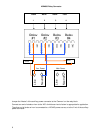
Most applications for the Bacharach HGM300/RDM800 monitor systems will consist of a single HGM300 and a
single RDM800.
The HGM300 should be mounted in the mechanical room and the RDM800 should be located in a control room, on
an outside wall of the mechanical room or at least, just inside the door to the mechanical room.
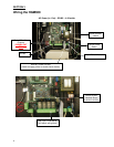
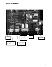
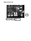
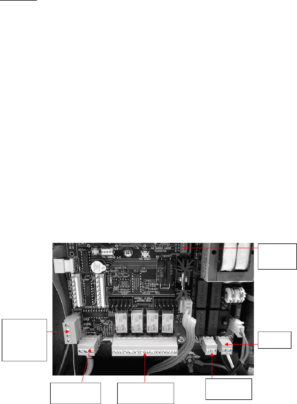
Connect power to the HGM300 using the two-lead connector on the far right bottom of the power supply PC board.
Make the ground connection to the screw post provided on the HGM300 door.
Auxiliary power to supply 120 VAC for wiring alarms is available from the second two-lead connector located to
the left of the main power connector.
Connect any alarms required to the four-relay connector marked “LEAK, SPILL and EVACUATE”. Connect the
“SYSTEM FAULT” relay if used.
The dual 4-20mAdc output connector is located on the left side of the HGM300 main PC board. This is a SIGNAL
OUT ONLY function. Both loops must be wired if this option is installed. If only one loop is used, the unused loop
must be shorted out.
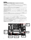
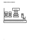
Connect power to the RDM800 by removing the four screws holding the front panel to the RDM800 chassis. Turn
the front panel over and locate the two-lead connector on the far right bottom of the PC board. Make the line and
neutral connections and attach the ground to the screw post provided on the panel.
Connect any alarms to the two-relay connector located on the bottom center of the RDM800 PC board.
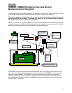
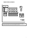
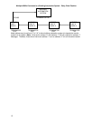
The RS-485 communication wiring between the HGM300 and RDM800 must be connected in the following
manner:
Locate the RS-485 connector marked “TO MONITOR” on the RDM800. This connector should be on the far-left
bottom of the RDM800 PC board. Connect one lead of a twisted shielded pair to the “B” connection point (the far
left point), note the wire color. Connect the second wire to the “A” connection point (the middle), note the wire
color. Connect the ground to the “GND” connection point.
Make the wire run to the HGM300 and connect the twisted shielded pair to the HGM300 RS-485 connector using
the same color code as used on the RDM800.
NOTE: With a basic system consisting of a single HGM300 and a single RDM800 the position of the
“Terminators” switches is not critical.
NODE
ADDRESS
SWITCH
RS-485
CONNECTOR
A
LARM & FAULT
RELAYS
AUXILIARY
POWER
DUAL
4-20 MA DC
OUTPUT
SIGNAL OUT
ONLY
MAIN
P
O
WER
6