SECTION 5
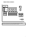
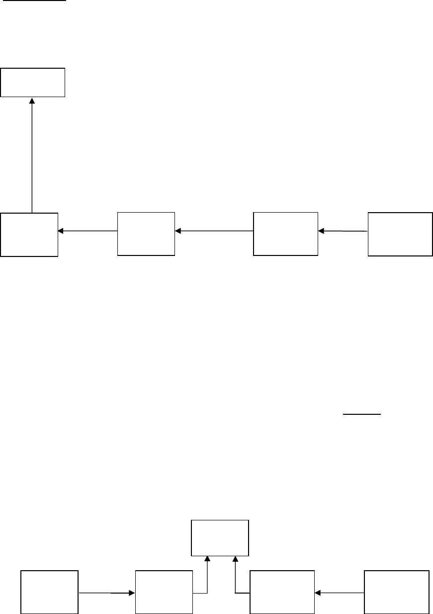
Multiple HGM’S
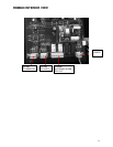
TERMINATOR
“IN” MULTIPLE HGM300’S WITH RDM800
RMD800
NOTE – THE LAST HGM300 OR RDM800 ON EITHER END OF THE
NETWORK MUST HAVE THE TERMINATOR IN THE “IN” POSITION AND ALL
OTHER UNITS MUST HAVE THEIR TERMINATORS IN THE “OUT” POSITION.
NOTE – TOTAL LENGTH OF RS-485 CABLE CANNOT EXCEED 1500m. (Use
instrument cable 20 gage multistrand shielded and twisted pair – similar or equal
to Beldon cable #8762.)
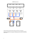
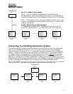
RS-485 RS-485 CONNECTIONS BETWEEN HGM300’s
THE RDM800 AND HGM300 UNIT 4 TERMINATOR MUST BE IN THE “IN”
POSITION. HGM300 UNITS 1, 2, & 3 MUST BE IN THE “OUT” POSITION.
HGM300
UNIT 1
NODE 1
HGM300
UNIT 4
NODE 4
HGM300
UNIT 3
NODE 3
HGM300
UNIT 2
NODE 2
TERMINATOR TERMINATOR TERMINATOR TERMINATOR
“OUT” “OUT” “OUT” “IN”
Connecting To A Building Automation System
The HGM300 may be connected to a building automation via the RS-485 connector. The node address
switch on each HGM300 may be set from “0” to “16” in order to conform to the building automation
system requirements. Units set to a “0” or “1” address both respond to messages from the RDM800 as
address “1” therefore you should not have a unit set to “0” and another set to “1” on the same network. If
the HGM300 network is connected directly to a building automation system it
may not be connected to
the RDM800. However, the RDM800 has two communications ports, an “upstream” port (labeled TO
BMS) and a “downstream port (labeled TO MONITORS). A BMS node may be connected to the upstream
RDM800 port while the downstream RDM800port talks to the HGM300’s. In this case, the BMS is talking
“through” the RDM800 to the HGM300’s, but not physically on the HGM300/RDM800 network.
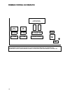
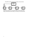
Note – If the HGM300 is not at the end of the line in a series connection, then the terminator on the HGM
must be set to “OUT.” Also, each end of the network must have the terminator set to “IN”.
TERMINATOR
“OUT”
HGM300
NODE 2
BMS
HGM300
NODE 4
HGM300
NODE 3
HGM300
NODE 1
TERMINATOR TERMINATOR TERMINATOR TERMINATOR
“IN” “OUT” “OUT” “IN”
11


