


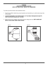
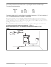
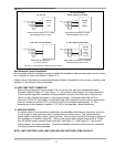
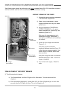
CONTROL WIRING
NOTE: Wiring to the low-voltage controls should not run in the same conduits as the power supply
wiring because faulty signals could result.
The use of either a metal conduit or shielded wire is required for all the control and / or safety wiring.
When using metal conduit, the conduit must extend the entire length of the wire, and the conduit must
be grounded at the humidifier cabinet. If the conduit does not extend the entire length of the control
wire, the wiring must be shielded and the following guidelines must be used:
1. The wire shields and all unused conductors must be grounded externally to the humidifier cabinet.
2. Ensure a good connection between the shields / conductors and the metal bar of the humidifier
cabinet.
Additionally, a supplied ferrite core must be installed around the control wiring between where the wire
enters the humidifier cabinet and the low voltage terminal block.
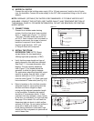
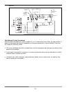
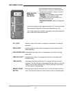
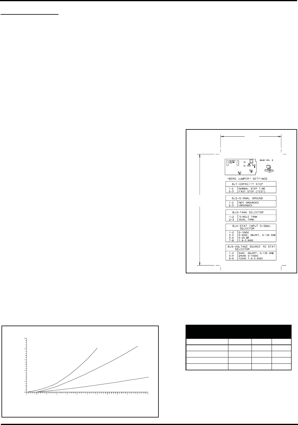
9) CONTROL HUMIDISTAT
The Series EHU-700 is capable of accepting controls
signals with the following characteristics:
a. 0-10 Vdc Humidistat
(Part No. A18609 and A18610) (H200 or H270 series)
b. 1.9-3.9 Vdc Humidistat
(Part No. C1471 or C1472)
c. 4-20mA, 250 Ω input impedance.
d. 0-10 Vdc, 50 kΩ input impedance.
e. 0-5 Vdc.
f. 0-135 ohms.
g. on/off
To adapt the EHU-700 to these different types of control humidistats, jumper BJ4 and BJ5 on the print-
ed circuit board (Figure 9-1) must be manually changed and the humidistat must be wired to the
appropriate connections of terminals 1, 2 & 17. Refer to Figure 9-1 or the sticker on the inside of the
cabinet for proper jumper locations.
9
3"
(75 mm)
5-1/2"
(
140 mm)
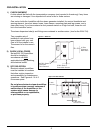
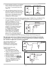
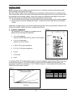
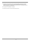
Pressure Loss in Copper Pipe
(40' Equivalent Run)
1-1/4"
1-1/2"
2"
12
0
#/Hr. Steam
1
2
3
4
5
I
n. WC
110
100
90
80
70
60
50
40
30
20
10
Fitting 1-1/4 1-1/2 2
45° Elbow 1.0 2.2 2.8
90° Elbow 2.5 4.3 5.5
90° Long Elbow 1.5 2.7 3.5
Tee 5.0 9 12
Feet of equivalent copper pipe for copper
pipe fittings
Figure 9-1
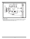
Figure 9-2
Chart 9-1