


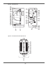
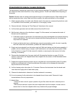
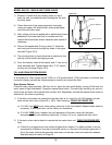
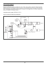
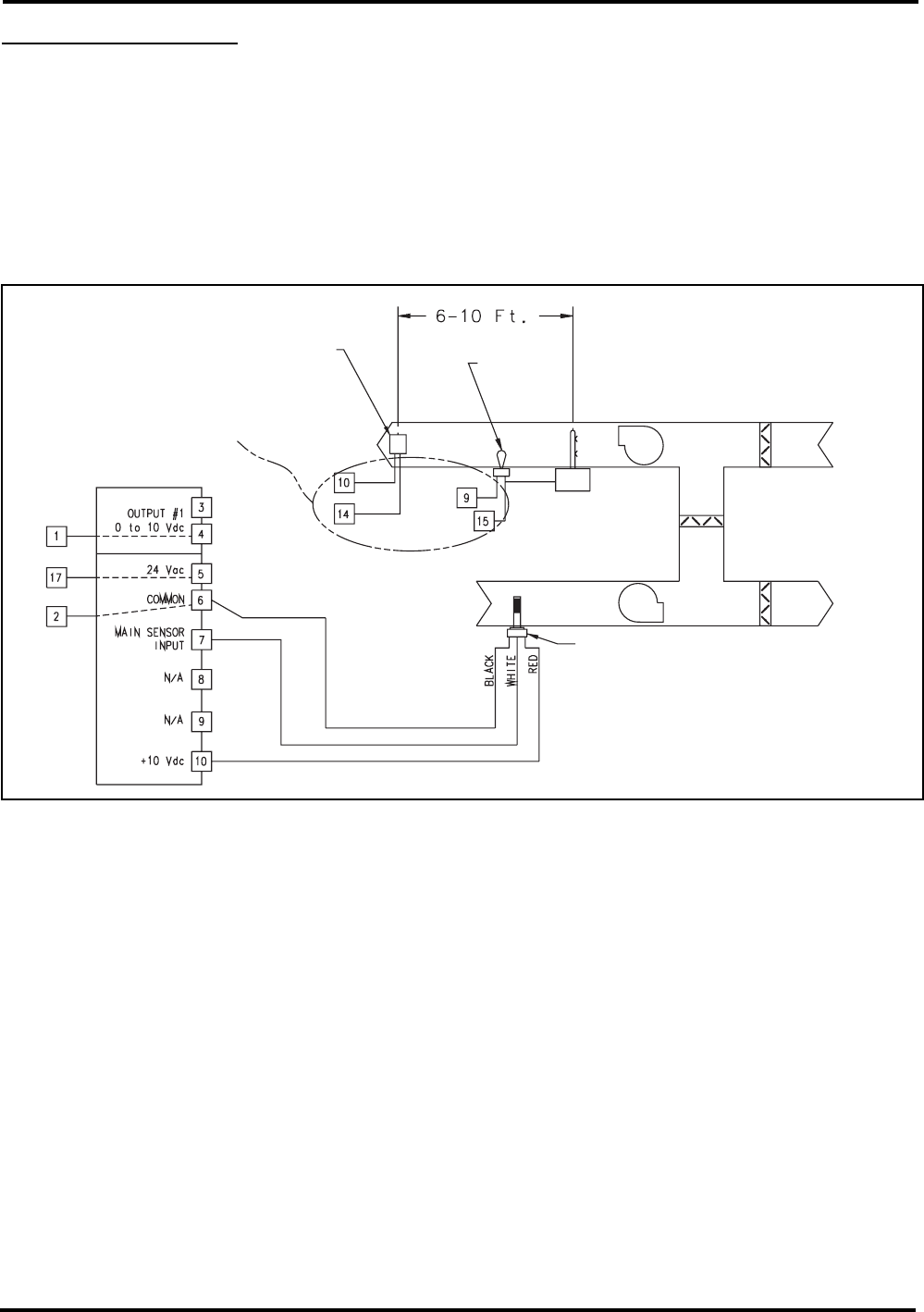
APPLICATION EXAMPLE
Steam humidification system controlled by a 0 to 10 Vdc valve wired to output #1. Remote humidity
display using 0 to 5 Vdc signal is wired to output #2. The humidity sensor is located in the return air
duct. A proportional high limit humidity sensor is installed in the supply duct. An outdoor temperature
sensor is installed in the fresh air duct.
Humidistat model number: H270-69-13-10-31
figure 42-1. Alternative humidistat wiring A17898 (H270)
39
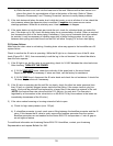
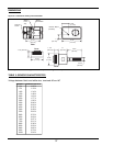
On/Off
High Limit
Humidistat
(optional)
Air Flow
Switch
(optional)
Main Humidity Sensor
H
umidifier
C
onnections
Humidifier
Location
Outside Air
Exhaust A
ir
Humidifier
Connection
Terminals