


TROUBLESHOOTING GUIDE
CAUTION!: Disconnect the electric power supply at the circuit breaker or switch whenever the
unit is to be inspected or serviced. DO NOT USE THE TANK ON/OFF SWITCH ON THE HUMIDI-
FIER BECAUSE THIS SWITCH DISCONNECTS THE STEAM GENERATOR TANK ONLY.
PRINCIPLE OF OPERA
TION - AN OVERVIEW
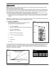
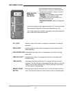
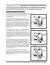
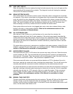
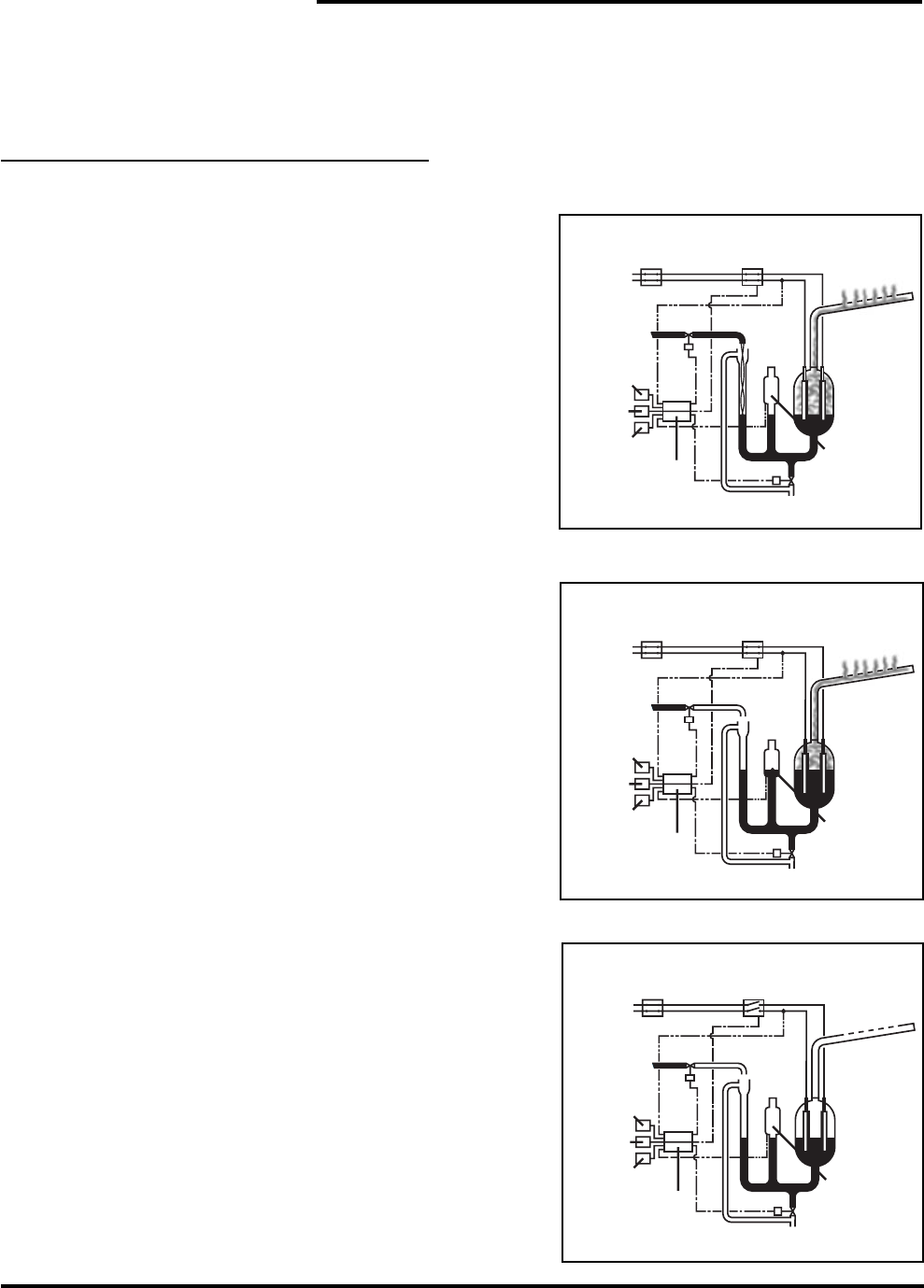
The Armstrong Series EHU-700 electronic steam humidifier Figure 17-1
converts ordinary tap water to steam and distributes it within
the air being humidified to bring the relative humidity up to
the desired level.
The humidity demand is sensed by the humidistat. A micro-
controller converts this demand signal into an amperage
requirement. If humidistat demand is above 35%, the internal
power contactor closes, applying voltage to the electrodes,
and the fill valve opens to begin filling the tank. Water enters
the bottom of the steam generator tank and rises until it
reaches the electrodes. Upon contact, electrical current flows
through the water, causing it to boil and produce steam
(Figure 17-1).
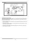
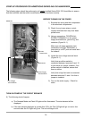
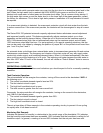
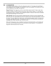
As the water level rises (Figure 17-2) increased electrical
Figure 17-2
current flows through the water, producing more steam. This
increase will continue until the desired current level (i.e.
required steam output) is reached. At this point, the fill valves
will cycle off and on to maintain the desired amperage ±5%.
The desired current level is a function of the nominal current
rating, humidistat demand, and the automatic capacity adjust-
ment feature.
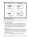
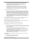
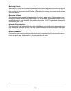
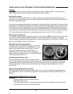
When the humidistat senses the added moisture in the air,
the demand for humidity begins to drop. As the demand
drops, the output of the unit is modulated down by boiling
away water and not filling. This allows the amperage to
decrease, thereby reducing the steam flow. The fill valve can
then cycle at the lower steam output (current) requirement.
When the humidistat demand signal drops below a minimum
Figure 17-3
25% demand, the contactor is de-energized, and steam out-
put stops (Figure 17-3).
Steam output may also be stopped by a duct high-limit
humidistat or a fan interlock switch. These devices prevent
excess moisture and condensation in the duct by opening the
tank contactor if there is too much humidity or insufficient air-
flow within the duct.
17
External
Disconnect
Controlling
Humidistat
High-Water
Float Switch
Drain Valve
Distribution
Tu be
Overflow
Line
Controller
Fan Interlock
High-Limit
Humidistat
Fill Cup
Fill Valve
Current Sensor
Line
Internal
Power
Contactor
External
Disconnect
Controlling
Humidistat
High-Water
Float Switch
Drain Valve
Distribution
Tu be
Overflow
Line
Controller
Fan Interlock
High-Limit
Humidistat
Fill Cup
Fill Valve
Current Sensor
Line
Internal
Power
Contactor
External
Disconnect
Controlling
Humidistat
High-Water
Float Switch
Drain Valve
Distribution
Tu be
Overflow
Line
Controller
Fan Interlock
High-Limit
Humidistat
Fill Cup
Fill Valve
Current Sensor
Line
Internal
Power
Contactor