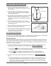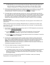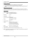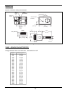
If the electrodes begin to disintegrate, the tank may turn black or red, and arcing or flashing
may be visible inside the tank while it is operating. IF YOU NOTICE EXCESSIVE ARCING,
SHUT THE UNIT OFF AND CALL THE FACTORY BEFORE RE-STARTING UNIT.
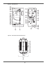
To replace the electrodes, please refer to the "Tank Disassembly and Electrode Replacement"
Section of this manual. (Page 33)
RECOMMENDED PROCEDURE FOR STEAM GENERATOR TANK AND ELECTRODE
REMOVAL, CLEANING, REPAIR AND REPLACEMENT
TANK REMOVAL AND REPLACEMENT - ALL MODELS
1) Turn steam generator tank off by pressing tank off button.
2) Drain the tank by pressing the drain button. It may take five minutes for a full tank to completely
drain.
3) Once the tank is completely empty, turn off the power at the main disconnect or breaker.
4) Disconnect the steam hose from the top of the steam generator tank by loosening the hose clamp
with a screwdriver or 5/16" nutdriver. BE CAREFUL! The tank may still be hot to the touch, and
some steam may still be condensing in the tank.
5) Disconnect the power leads at the steam generator with a 7/16" wrench (three leads for 3-phase
units, two leads for single phase). See wiring diagram, Figure 12-1, for more details.
6) Remove the tank from the cabinet by lifting it out of the drain adaptor. BE CAREFUL! The tank
may still contain hot steam or condensate.
7) It is preferable that you replace the tank with a new or rebuilt unit and take the current tank to the
shop for servicing.
8) Install the tank into the EHU by lowering it into the drain adaptor. A small amount of high tempera-
ture grease or silicone lubricant may be used on the drain adaptor o-ring to help it seal properly.
After a couple of tank replacements the o-ring should de replaced as well.
9) Connect power leads and, on EHU-703 and 704, the loose end of the jumper wires to electrode
studs using a 7/16" wrench (three leads for 3-phase units, two for single phase). Refer to the
wiring diagram in your unit for specific information.
10) Connect the steam hose to the top of the steam generator with the hose clamp.
11) Check all wiring connections at the main power, contactor, and control voltage terminal blocks
(Figure 14-1), as well as on the generator itself. Energize the circuit breaker or main disconnect.
Refer to Start-up Section if you encounter any problems when restarting the unit.
30


