


TANK DISASSEMBLY, CLEANING, AND ELECTRODE REPLACEMENT
MODELS EHU-703 AND 704, SINGLE AND THREE PHASE
1) Using a 7/16" wrench, disconnect the jumper wires from the steam generator.
2) Remove 24 metal clips by pushing gently on top of each clip with a screwdriver while cupping the
clip with the other hand.
3) Lift the top half of the tank free of the bottom half and rest it on the electrodes. Use a ¾" wrench
to loosen and remove the nuts from the six electrode studs.
4) Lift the top tank half from the electrodes. Remove the o-ring from the lower tank half o-ring
channel and put it aside for re-use. On high voltage units, lift the barrier assembly out of the
bottom tank half.
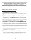
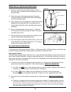
5) Clean the tank halves and the barrier assembly (Figure 35-1), if applicable, using a scraper, stiff
bristle brush, and/or water spray. Rinse the unit with clear water. If necessary, the drain screen
may be removed for cleaning by removing three screws and pushing up through the bottom tank
connection with a screwdriver handle or other blunt object. The drain screen snaps back into place
and is SECURED BY THE 3 SCREWS after cleaning. BOTH THE BARRIER ASSEMBLY AND
THE DRAIN SCREEN SHOULD BE REPLACED WITH NEW PARTS IF THEY ARE
UNSERVICEABLE.
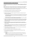
6) Install one electrode in the top tank half. Make sure the small o-ring is located at the bottom of the
electrode stud. Push the electrode through one of the holes in the upper tank half. Slowly turn the
electrode until it locks in place. Thread a nut, finger tight, onto the electrode stud. Repeat this
process with the other five electrodes.
7) Turn the tank top half upright and rest it on the electrodes. Tighten the nuts on all the electrode
studs with a ¾" wrench, so they are just snug.
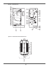
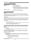
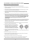
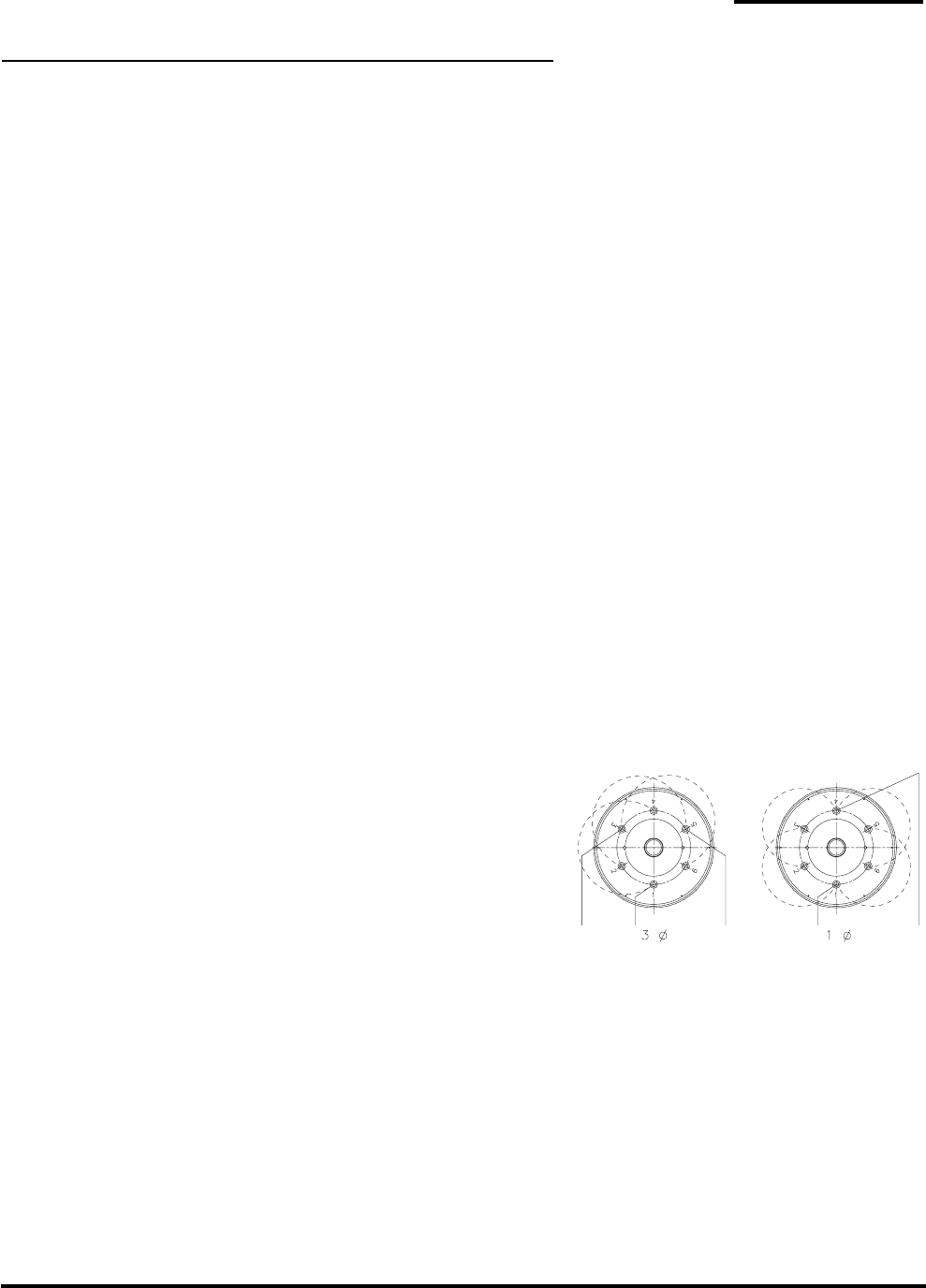
8) Install the electrode jumper wires to the studs at the
top of the tank. Fasten one end of the jumper wire with
a washer and a 1/4" hex nut, using a 7/16" wrench.
There are three jumpers on a three-phase unit, and
four jumpers on a single phase unit. On a single phase
unit you should have only two loose ends ( Figure 34-1).
9) Install the o-ring in the bottom tank half o-ring channel.
A third hand or weight may be needed to hold one end of the o-ring in place while the other end is
being installed.
10) Install the barrier assembly in the bottom tank half.
11) Lower the top tank half onto the bottom tank half. Line up the marks on the rim of the top and
bottom tank halves to properly center the electrodes.
12) Look trough the top connection to make sure the o-ring is still in place.
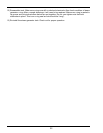
13) Snap a metal clip over the flanges of the tank halves, midway between two alignment marks.
Position another clip on the opposite side of the tank. Install all 24 clips in this manner.
33
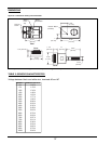
Figure 34-1.