


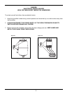
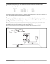
6) WATER FILL SUPPLY
Connect the unit to the building water supply (25 to 125 psig pressure). Install a shut-off valve
near the humidifier. Connect the water supply to the 3/8" tube compression fitting on the fill valve
adaptor.
NOTE: ORDINARY (POTABLE) TAP WATER IS RECOMMENDED. IF POTABLE WATER IS NOT
AVAILABLE, CONSULT THE FACTORY (SEE "WATER QUALITY AND TREATMENT SECTION OF
THIS MANUAL, PAGE 23, FOR MORE INFORMATION). DO NOT USE BRACKISH OR CONTAMI-
NATED WATER.
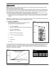
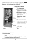
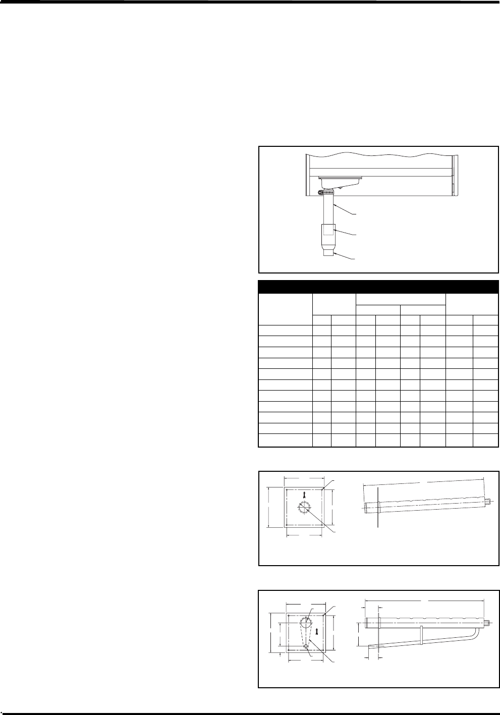
7) CONNECT DRAIN
Connect to a suitable waste draining
system. Use the clear drain hose provided
and a 1" copper pipe (Figure 7-1), pitched
1"per foot. The drain water may be as hot
as 160°F. Drain it where it will not present a
hazard to personnel. An air gap to prevent
backflow is required if drain water is
required to be less than 140°F, use
of Temp-R-Drain will be required.
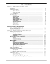
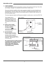
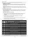
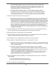
8) INSTALL THE STEAM
DISPERSION TUBE NOTE: Please
contact factory for duct applications
offering high static pressures (>4"WC).
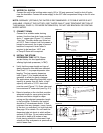
a. Verify that the proper length and type of
steam dispersion tube has been selected:
See Chart 7-1 for proper dispersion tube
lengths. The low capacity dispersion
tube (Figure 7-2) is sloped toward the
generator to allow for gravity drainage.
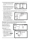
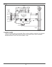
On applications where the humidifier output
capacity is greater than 40 Ibs/hr, a high
capacity tube with a ½"O.D. drain tube
must be used (Figure 7-3). Drain tube must
have minimum 6" water seal (see Fig. 8-3).
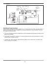
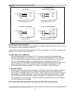
b. Select a location on the duct that provides
adequate length for vapor mixing and the
shortest connection length for vapor
mixing and the shortest connection length
to the humidifier. Preferably the location
should be 6" downstream and/or 10 feet
upstream from any dampers, vanes, bends
in the duct, or controllers (i.e. high limit stat).
See page 10 for details. Do not install the
dispersion tube into ducts in which airflow
exceeds 2,000 fpm. Do not restrict airflow in
ducts with a depth of 8 inches or less.
Avoid placing manifold in downward, high
velocity air flow as dynamic air pressure will
restrict steam flow.
7
1" I.D. Clear Hose
Supplied with Unit
Fit Hose Inside
1-1/2" Pipe
1" or Larger
Copper Pipe
L
For Steam Capacity
40 lb/hr or Less
5.25
6
.00
6.00
Ø.22
4 Places
5.25
Ø1.75
Hole in Duct
6.00
6
.00
R.88
3.50
1.50
Ø.22
4 Places
1.00
5.25
R.37
5.25
2.00
3.50
For Steam Capacity
Above 40 lb/hr
Hole in Duct
L
Figure 7-1
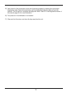
Chart 7-1. Selecting Proper Steam Dispersion Tube
Steam
Steam Disp. Duct Width
Weight
Disp. Tube Tube Length Min. Max.
Model No.
in mm in mm in mm lb kg
D-1 12 304 11 279 16 406 3 1.4
D-1.5 18 457 17 432 22 559 3 1.4
D-2 24 609 23 584 34 864 4 2
D-3 36 914 35 889 46 1168 6 3
D-4 48 1219 47 1194 58 1473 8 3.6
D-5 60 1524 59 1499 70 1778 9 4
D-6 72 1829 71 1803 82 2083 10 4.5
D-7 84 2133 83 2108 94 2388 11 5
D-8 96 2438 95 2413 106 2693 12 5.5
D-9 108 2743 107 2718 118 2998 13 6
D-10 120 3048 119 3023 130 3302 14 6.4
Figure 7-2
Figure 7-3