


26
installation
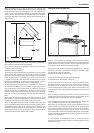
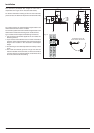
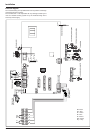
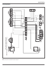
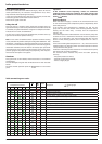
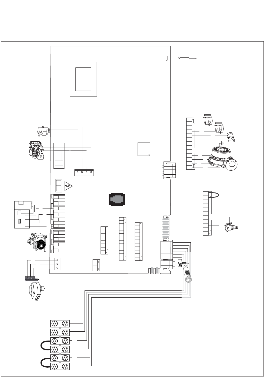
Electrical diagram
For increased safety, ask a quali ed technician to perform a thorough
check of the electrical system.
The manufacturer is not responsible for any damage caused by the
lack of a suitable earthing system or by the malfunctioning of the
electricity mains supply.
5
1
Display
Detection electrode
LN
VALVOLA
GAS
ACCENDITORE
FLAME
PUMP
ZONE1
FILLING
PUMP
SPEED
1
1
FUSE 2AT
1 23 4 1 23 456
1
234
1
1
TA1 TA2
RdRdBkBk
Diverter valve
(only E-COMBI)
Bk
Bl
Br
3
1
2
4
1
Circulation pump
Bk
Bk
Bk
Bk
CN11
CN16
CN24CN12
1213 1110 9 8 7 6 5 4 3 2 1
1110 9 8 7 6 5 4 3 2 1
2
1
87654321
Gas valve
Spark generator
Bl
Bl
Br
Br
Fan
C.H. Flow temperature probe
CN24
C.H. Return temperature probe
Thermal fuse
Low water pressure switch
1312 11 10 9 8 7 6 5 4 3 2 1
Bl
Bl
Rd
Bk
Rd
Wh
Rd
Br
Br
Br
Bl
CN12
1110987654321
Bk
Br
BkBk
D.H.W. Flow Switch
(only E-COMBI)
Bk= Black
Rd = Red
Gr = Green
Bl = Blue
Br = Brown
Wh = White
Gry = Grey