


15
installation
A
A
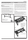
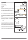
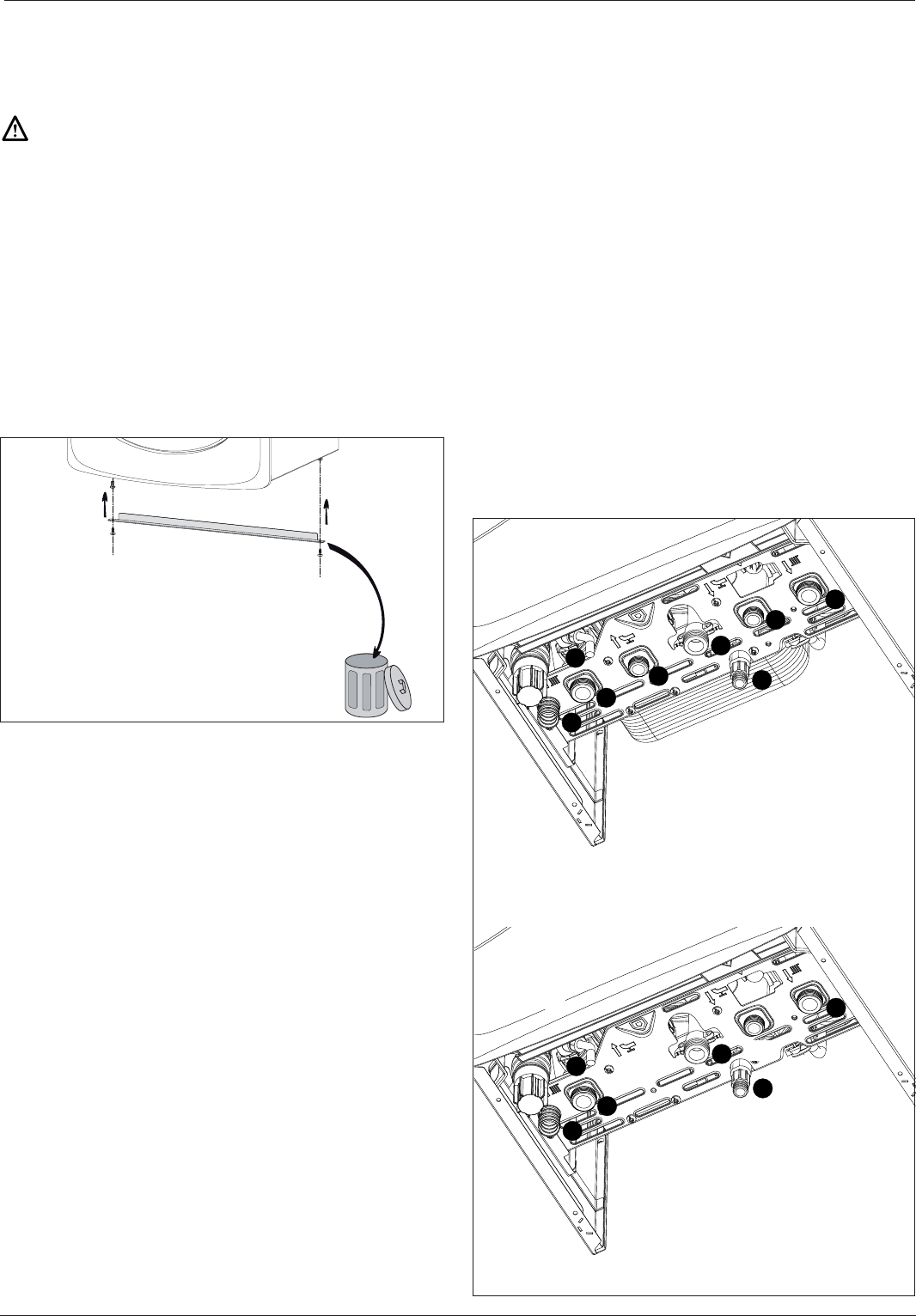
- remove the 2 screws A from the
transport bar
- dispose of the transport bar and
reassemble the xing screws.
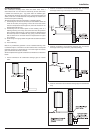
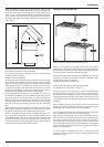
Safety Valve Discharge and Condense Outlet
The pressure relief valve pipe is made of copper. It should terminate
below the boiler safely outside the premises. Care should be taken
that it does not terminate over an entrance or window or where a
discharge of heated water could endanger occupants or passers by.
Warning !
Do not apply heat to the copper safety valve outlet pipe whilst it
is connected to the 3 bar safety relief valve.
Fill the central heating and DHW system and bleed air from the system
as described in the Commissioning instructions (page 30).
The system should be carefully checked for leaks, as frequent re lling
could cause premature system corrosion or unnecessary scaling of
the heat exchanger. The pipe from the trap should be connected to a
drain as described in the relevant regulations.
Pay special attention not to bend the condensate drain pipe in such
a way as to interrupt the ow. Please only use drain pipe material
compatible with condensate products (refer to BS 6798:2009).
The condensate ow can reach 2 litres/hour because of the acidity of
the condensate products (Ph close to 2), take care before operation.
See page 13 for condensate discharge options.
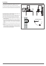
Gas connection
Make sure, using the labels on the packaging and the data plate on
the appliance itself, that the boiler is in the correct country and that
the gas category for which the boiler was designed corresponds to
one of the categories available in the country where it will be used.
The gas supply piping must be created and measured out in
compliance with speci c legal requirements and in accordance with
the maximum power of the boiler; you should also make sure that the
shut-o valve is the right size and that it is connected correctly.
Check that the supplied gas corresponds to the type of gas for which
the boiler was designed (see the data plate located on the appliance
itself).
It is also important to check that the pressure of the gas (methane
or LPG) you will be using to feed the boiler is suitable, because if it
is insu cient the power may be reduced, causing inconvenience for
the user.
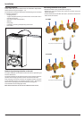
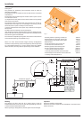
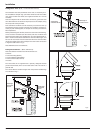
Water connection
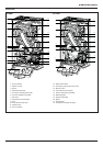
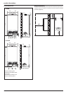
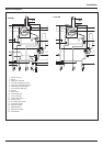
The illustration below shows the connections for the water and gas
attachments of the boiler. See valves con guration on page 14.
Check that the maximum water mains pressure does not exceed 6 bar;
if it does, a pressure reducing valve must be installed.
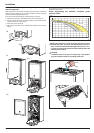
For the measuring of the pipes and of the heating bodies in the
heating system, the residual head value should be calculated as a
function of the requested ow rate, in accordance with the values
shown in the circulation pump graph (page 16).
$
%
&
'
(
,
+
)
$
&
(
,
+
)
A. Central heating Flow
B. Domestic Hot Water Outlet
C. Gas Inlet
D. Domestic Cold Water Inlet
E. Central Heating Return
F. Safety Valve Discharge
H. Drain Valve
I. Drain condensate
E-COMBI
E-SYSTEM
*
* - Connection for Filling Loop