


25
installation
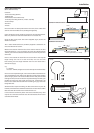
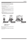
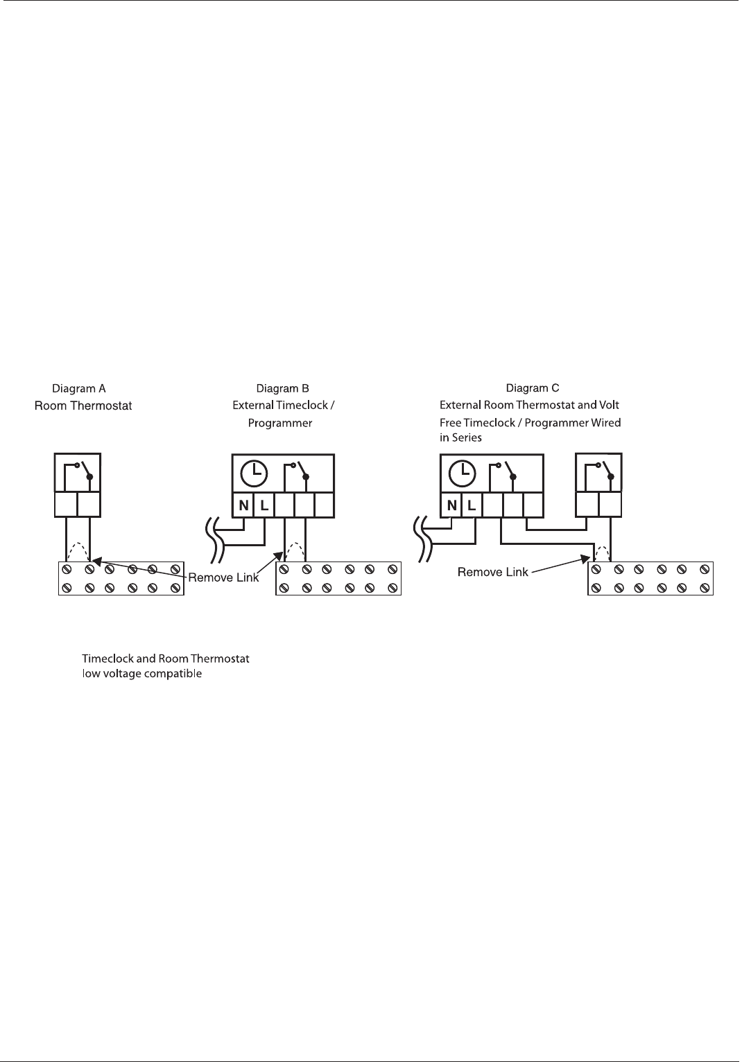
Room Thermostat / Remote Clock Connection
The boiler connections for external controls are 12V DC and so only
controls of 12V DC that have voltage free contacts should be used.
The boiler connections for external controls are 12V DC and so only
controls of 12V DC that have voltage free contacts should be used.
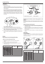
To connect a room thermostat, it is necessary to:
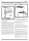
1. Open the control panel
2. Loosen the cable clamp using a screwdriver and insert the wires
leading from the room thermostat
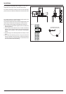
3. Connect the wires to the terminals as indicated in the gure below,
removing the link
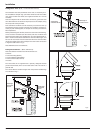
4. If a remote time clock is to be tted, (using a volt free switching time
clock) connect the switching wires from the time clock following
points 1 - 3 above (Disconnect internal time clock)
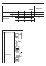
5. If using an external time clock and room thermostat, these must be
connected in series as shown in diagram C, (Disconnect internal
time clock)
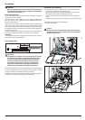
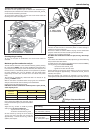
6. Ensure that they are well connected and not subject to stress when
the control panel is closed
N
OTE: WHEN CONNECTING THE BOILER TO EXTERNAL CONTROLS, DO NOT RUN 240V
CABLES FOR SWITCHING CIRCUITS (WHICH ARE LOW VOLTAGE) TOGETHER USE
SEPERATE CABLES TO PREVENT INDUCED VOLTAGE ON THE LOW VOLTAGE CIRCUITS.
Note: y plan system switch 240v and are therefore not suitable
system control systems unless a suitable relay is used to switch the
low voltage control circuit.
Do not connect 240v to the TA1 switching circuit. Connectiong 240v
to the TA1 switching circuit will damage th P.C.B. and invalidate
appliance warranty.
Connector TA on Terminal block
(low voltage switching)
Connector TA on Terminal block
(low voltage switching)
Connector TA on Terminal block
(low voltage switching)