


20
installation
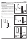
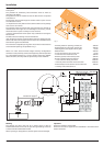
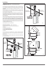
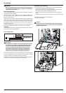
Once the boiler has been positioned on the wall, it is necessary to in-
sert the Ø80/125 adaptor (Fig. 5) for both horizontal and vertical ue
runs into the boiler ue socket (not supplied with ue kit - Part No
3318095).
Push the adaptor onto the boiler’s ue connection, grease the seals
then add extensions or elbows as required, secure the adaptor, using
the clamp and screws provided.
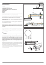
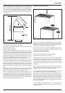
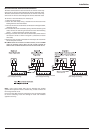
To t extensions or elbows it is rst necessary to ensure that the lip
seal is tted correctly into the inner ue, once veri ed, it is simply ne-
cessary to push them together, no clamps are necessary to secure the
ue components.
Before proceeding to t the ue, ensure that the maximum ue leng-
th has not been exceeded (see the tables) and that all elbows and
bends have been taken into consideration. For each additional 90° el-
bow 1 metre must be subtracted from the maximum ue length, and
for each 45° 0.5 metres must be subtracted from the maximum ue
length (the height of the vertical adaptor and a 45° bend can be seen
in Fig.6 and a 90° bend in Fig. 7).
Note: DO NOT cut the vertical ue kit.
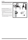
180 mm
Total length of
vertical kit 1240 mm
Useable length of
vertical ue 575 mm*
Fig. 5
Fig. 6
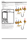
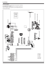
Fitting the 5” Flue (Ø 80 / 125 Horizontal/vertical)
Fitting the Coaxial Flue (Ø 60 / 100 Vertical)
Note: See table for maximum and minimum ue runs.
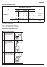
Contents:
1x Silicone O-Ring (60mm)
1x Conical Adaptor (60/100mm)
1x Vertical Flue Kit (80/125mm)
3x Screws
The vertical ue kit is supplied with a specially designed weather
proof terminal tted, which can be used either with a at roof or a
pitched roof.
The vertical ue kits useable lengths with the pitched roof ashings
are indicated in Fig. 7.
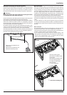
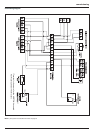
180 mm
Total length
of Vertical Kit
1355 mm
Useable length
of Vertical ue
690 mm*
Fig. 7