


19
installation
Warning
The exhaust gas ducts must not be in contact with or close
to in ammable material and must not pass through building
structures or walls made of in ammable material.
When replacing an old appliance, the ue system must be
changed.
Important
Ensure that the ue is not blocked.
Ensure that the ue is supported and assembled in accordance
with these instructions.
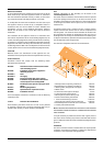
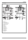
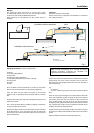
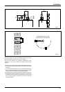
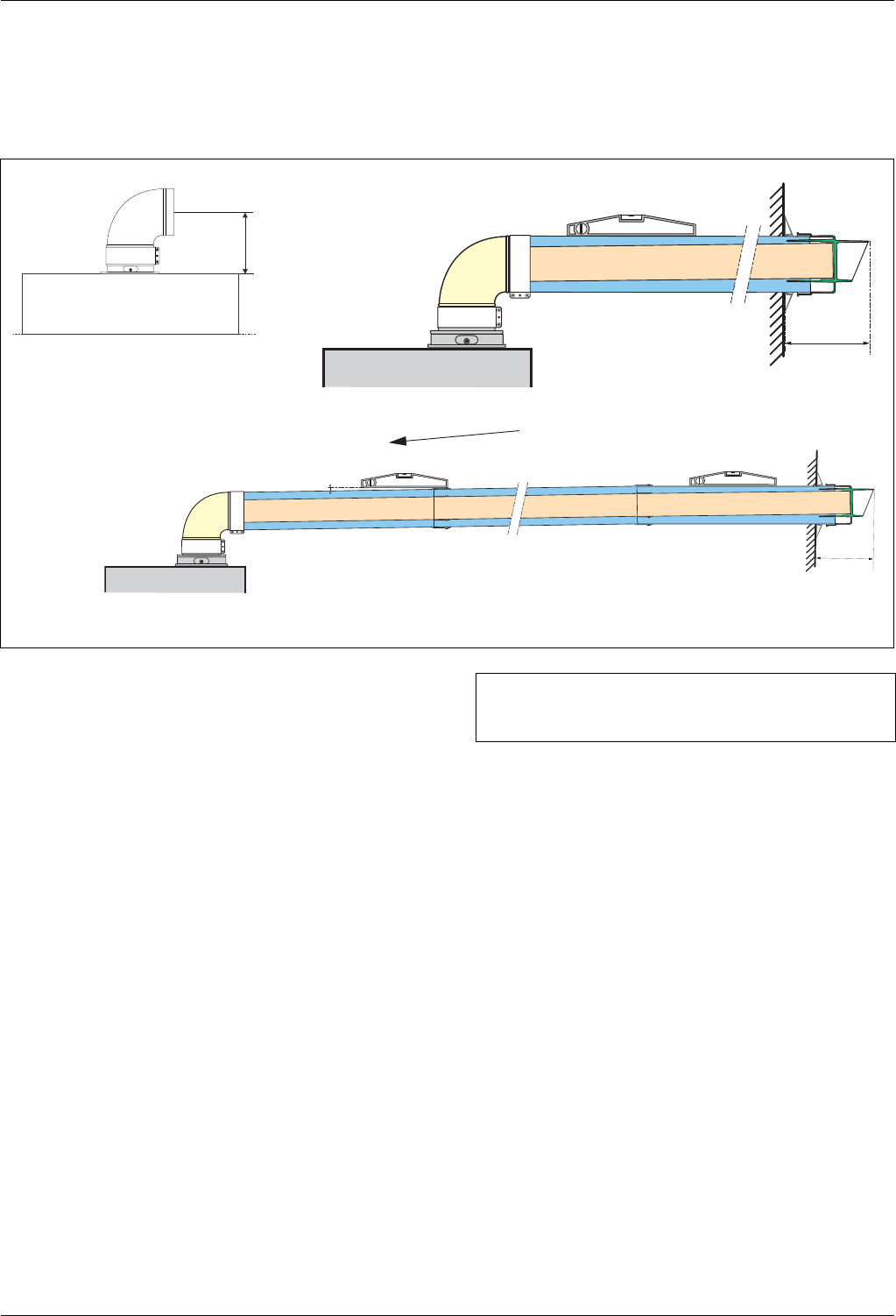
150 mm
118
* Min slope: 1˚
1˚= 17.5mm per metre
150 mm
* pente
Installation without extension
Installation with extension
Level
Level
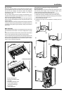
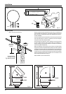
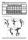
Fitting the Coaxial Flue (Ø 60 / 100 Horizontal)
Contents:
1x Silicone O-Ring (60mm)
1x Elbow (90°)
2x Wall Seals (Internal & External)
1x Flue Pipe including Terminal (1 metre - 60/100)
2x Flue Clamps
4x Screws
2x Seals
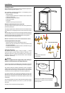
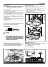
Once the boiler has been positioned on the wall, t the rubber
ue seal into the internal ue turret (see diagram opposite),
Insert the elbow into the socket and rotate to the required
position. note: It is possible to rotate the elbow 360° on its vertical
axis.
Using the ue clamp, seals and screws supplied (Fig 4) secure the
elbow to the boiler.
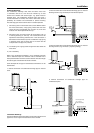
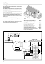
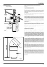
The 1 metre horizontal ue kit (3318073) supplied is suitable for
an exact X dimension of 753mm.
Measure the distance from the face of the external wall to the face
of the ue elbow (X - Fig 2), this gure must now be subtracted
from 753mm, you now have the total amount to be cut from the
plain end of the ue.
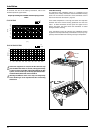
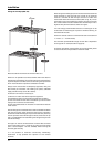
Draw a circle around the outer ue and cut the ue to the required
length taking care not to cut the inner ue, next cut the inner
ue ensuring that the length between the inner and outer ue is
maintained. (Fig 4).
e.g.
X = 555mm
753-555 = 198mm (Length to be cut from the plain end of the
ue).
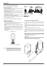
Once cut to the required length, ensure that the ue is free from
burrs and reassemble the ue. If tting the ue from inside of
the building attach the outer wall seal to the ue terminal and
push the ue through the hole, once the wall seal has passed
through the hole, pull the ue back until the seal is ush with the
wall. Alternatively, the ue can be installed from outside of the
building, the outer seal being tted last.
Should the ue require extending, the ue connections are push
t, however, one ue bracket should be used to secure each metre
of ue.
Note: See table for maximum and minimum ue runs.
slope
Fig. 3
Note: A Plume management kit is available for 60/100
horizontal termination. Instructions for installation are
supplied with the Plume management kit.