


14
installation
Installing the Boiler
Please check that you are familiar with the installation requirement
before commencing work (pages 11 - 15).
The installation accessories described in the following list are
included in the boiler packaging:
- Hanging bracket
- A paper template (showing the dimensions of the boiler with
5 mm side clearances)
- Connection valves (compression)
- Screws and washers
- Filling loop
- Installation, Servicing and User manual
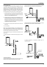
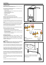
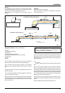
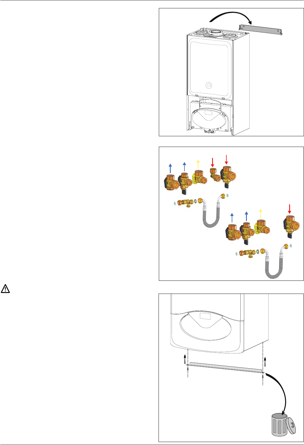
Method of positioning the boiler on the wall
The paper template can be used to ensure the correct positioning
of kitchen cabinets etc.
The paper template has to be xed to the wall and used to locate
the position of the hanging bracket and the centre for the ue
hole.
Drill and plug the wall and secure the hanging bracket using the
screws provided ensure the hanging bracket is level. Remove the
boiler from its packaging and remove the front casing panel.
Place the boiler on the hanging bracket.
N
OTE: THE APPLIANCE MUST NOT BE FITTED ON A COMBUSTIBLE WALL SURFACE.
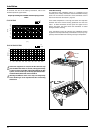
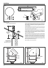
Connecting the boiler to the system
- Remove the boiler casing as described on page 15
- Remove the caps and connect the valves to the boiler using
the washers provided
- 5 x bre washers for the CH ow and return, cold water inlet, gas
and hot water outlet connections
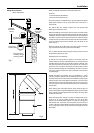
Safety Valve Discharge
The pressure relief valve pipe is made of copper. It should
terminate below the boiler safely outside the premises. Care
should be taken that it does not terminate over an entrance or
window or where a discharge of heated water could endanger
occupants or passers by.
Warning !
Do not apply heat to the copper safety valve outlet pipe
whilst it is connected to the 3 bar safety relief valve.
Fill the central heating and DHW system and bleed air from the
system as described in the Commissioning instructions (page 31).
The system should be carefully checked for leaks, as frequent
re lling could cause premature system corrosion or unnecessary
scaling of the heat exchanger. The pipe from the trap should be
connected to a drain as described in the relevant regulations.
Pay special attention not to bend the condensate silicone drain
pipe is such a way as to interrupt the ow. Please only use drain
pipe material compatible with condensate products (refer to BS
6798:2000).
The condensate ow can reach 2 litres/hour because of the acidity
of the condensate products (Ph close to 2), take care before
operation.
See page 13 for condensate discharge options.
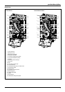
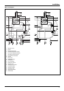
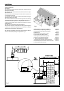
Note: Connections viewed from behind boiler
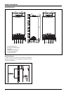
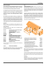
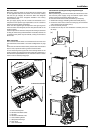
A
A
- remove the 2 screws A from the transport bar
- dispose of the transport bar and reassemble
the xing screws.
Note: Connections viewed from behind boiler
CLAS HE EVO
CLAS HE EVO SYSTEM
Note.
Connections viewed from
behind boiler.