


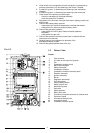
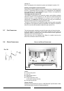
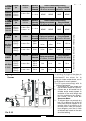
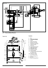
Ø 60/100 mm
F
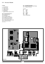
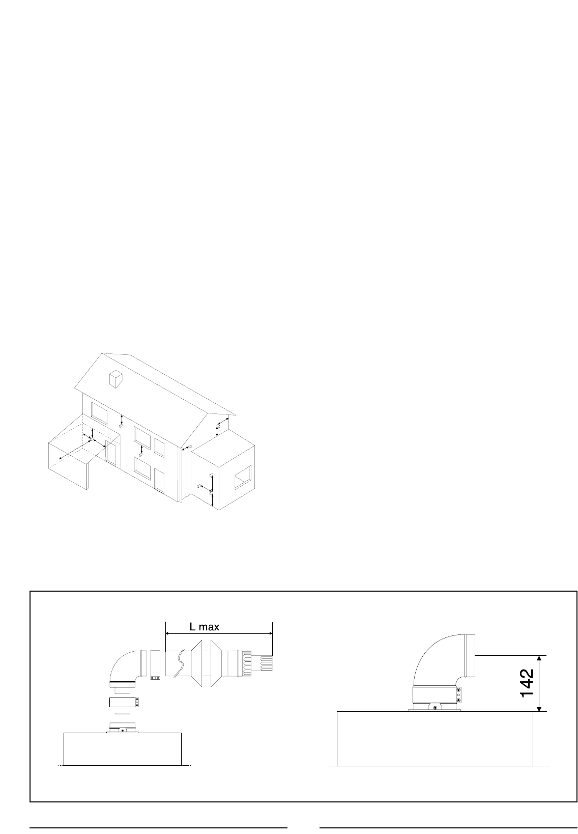
IG. 2.6
A
BC
D
E
F
G
J
K
HI
L
G
F
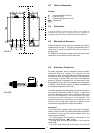
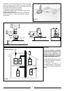
The boiler is designed to be connected to a coaxial flue discharge system.
9
2.9 FLUE CONNECTIONS
FLUE
SYSTEM
The provision for satisfactory flue termination must be made in accordance
with BS 5440-1.
The appliance must be installed so that the flue terminal is exposed to outside air.
The terminal must not discharge into another room or space such as an
outhouse or lean-to.
It is important that the position of the terminal allows a free passage of air
across it at all times.
The terminal should be located with due regard for the damage or
discolouration that might occur on buildings in the vicinity.
In cold or humid weather water vapour may condense on leaving the flue
terminal.
The effect of such “pluming” must be considered.
If the terminal is less than 2 metres above a balcony, above ground or above
a flat roof to which people have access, then a suitable terminal guard must
be fitted. When ordering a terminal guard, quote the appliance model
number.
A suitable terminal guard is available from:
TOWER FLUE COMPONENTS
Morley Road
Tonbridge
Kent TN9 1RA
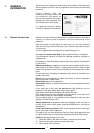
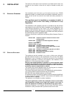
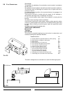
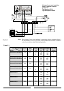
The minimum acceptable spacing from the terminal to obstructions and
ventilation openings are specified in F
IG. 2.5.
T
ERMINAL
P
OSITION
mm
A - Directly below an openable window or other opening 300
B - Below gutters, soil pipes or drain pipes 75
C - Below eaves 200
D - Below balconies or car-port roof 200
E - From vertical drain pipes and soil pipes 75
F - From internal or external corners 300
G - Above ground or balcony level 300
H - From a surface facing a terminal 600
I - From a terminal facing a terminal 1200
J - From an opening in the car port
(e.g. door, window) into dwelling 1200
K - Vertically from a terminal in the same wall 1500
L - Horizontally from a terminal in the same wall 300
FIG. 2.5