


For safety purposes, have a competent person carefully
check the electrical system in the property, as the
manufacturer will not be held liable for damage caused by
the failure to earth the appliance properly or by anomalies
in the supply of power. Make sure that the residential
electrical system is adequate for the maximum power
absorbed by the unit, which is indicated on the rating plate.
In addition, check that the section of cabling is appropriate
for the power absorbed by the boiler.
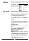
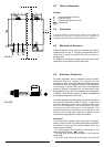
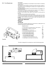
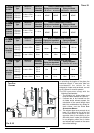
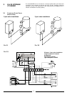
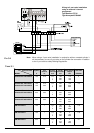
The boiler operates with alternating current, as indicated in
the technical information table in section 7, where the
maximum absorbed power is also indicated. Make sure
that the connections for the neutral and live wires
correspond to the indications in the diagram. The
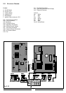
appliance electrical connections are situated on the
reverse of the control panel under the inspection cover
(see the servicing manual for further information)
IMPORTANT!
In the event that the power supply cord must be changed,
replace it with one with the same specifications. Make the
connections to the terminal board located within the
control panel, as follows:
- The yellow-green wire should be connected to the
terminal marked with the “”symbol;
- The blue wire should be connected to the terminal
marked “N”;
- The brown wire should be connected to the terminal
E
L
N
6
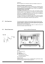
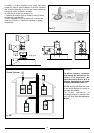
Fasten the boiler in place using the template and anchors
supplied with the unit. It is highly recommended that a
spirit level be used to position the boiler so that it is
perfectly level.
For additional information, please consult the instructions
contained in the connection kit and the flue kit.
2.6 ELECTRICAL CONNECTION
2.5 MOUNTING THE APPLIANCE
132 132
C
E
400 mm
300 mm
60 mm
450 mm
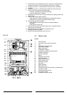
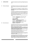
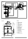
LEGEND:
A = Central Heating Flow (3/4”)
C = Gas Inlet (3/4”)
E = Central Heating Return (3/4”)
mm = Clearances
2.3 OVERALL DIMENSIONS
In order to allow for access to the interior of the boiler for
maintenance purposes, the boiler must be installed in
compliance with the minimum clearances indicated in F
IG. 2.1
2.4 CLEARANCES
F
IG. 2.1
F
IG. 2.2